
Circuit Diagram
Index 521
Voice control core circuit
Published:2011/8/30 2:12:00 Author:Christina | Keyword: Voice control, core circuit

This is a mature circuit, you don't have to worry about its reliability.
The sensitivity is very good, you can improve the sensitivity by increasing the value of R3, also you can reduce the sensitivity by reducing the value of R3. The core circuit is in the blue box, you can make good use of it, because it is transplantable.
(View)
View full Circuit Diagram | Comments | Reading(856)
Benchmark Voltage Source Circuit of Zero Temperature Coefficient
Published:2011/7/26 0:01:00 Author:Michel | Keyword: Temperature Coefficient, Voltage Source Circuit

Picture a and b are the benchmark voltage source circuits of zero temperature coefficient.Zero temperature coefficient of benchmark voltage chooses the work point of field effect transistor according to zero temperature coefficient points of UGS-ID characteristic curve. It uses the voltage drop of both ends,which makes the constant current diode of zero temperature coefficient work.Operational amplifier A1 (LM4250) is the same phase work state and its work current is determined by R4.RP1 is used to set benchmark voltage temperature coefficient, it can be chosen between in positive,negative and zero.RP2 is used to adjust the voltage slightly.All the resistor in the circuit needs to choose metalfilmresistor with good temperature characteristic.Picture (b) is different from picture (a) and its A1 input end is connected with VT2 and there are two kinds of output voltgae.
(View)
View full Circuit Diagram | Comments | Reading(854)
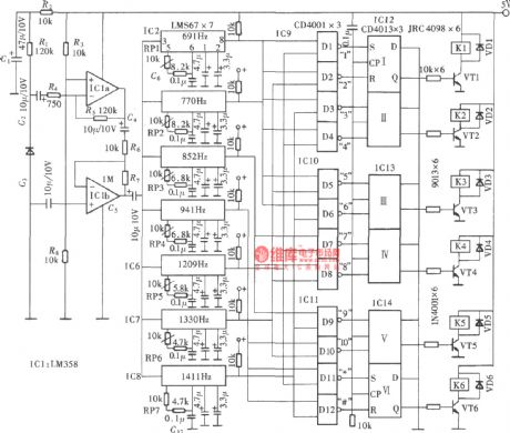
Sound and light double control eight-channel color light 12 songs sound circuit BH-SH-II
Published:2011/8/30 2:23:00 Author:Christina | Keyword: Sound, light, double control, eight-channel, color light, 12 songs, sound circuit

As the figure shows, it is composed of the voice-activated electronic switch, the light control switch, the music sound circuit, the audio power amplifier circuit, the multivibrator, the time order distribution circuit, the audio control switch circuit, the SCR drive circuit and the AC step-down rectifier circuit. When the circuit is playing the world famous songs, the eight-channel color light will send out the synchronous flash light.
(View)
View full Circuit Diagram | Comments | Reading(1627)
AN5539 field scanning output integrated circuit
Published:2011/8/23 22:38:00 Author: | Keyword: field scanning, output, integrated circuit


The AN5539 is designed as the field scanning output integrated circuit which is composed of the Panasonic company, and it can be used in all kinds of domestic and imported color TVs.
1.Features
The AN5539 has the field excitation and output circuit and the pump power control circuit. The maximum output current is 2.2Ap-p, the maximum output power is 15W. The typical application circuit of the manifold is as shown in figure 1-19.
2.Pin functions and data
The AN5539 uses the 7-pin single row DIP package, the 5-pin functions and data are as shown in table 1-19.
(View)
View full Circuit Diagram | Comments | Reading(9432)
Function generator circuit composed of the ICL8038
Published:2011/8/24 20:49:00 Author:Christina | Keyword: Function, generator
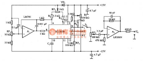
The function generator circuit which is composed of the ICL8038 is as shown in the figure. The ICL8038 is composed of the charging and discharging current source, the comparator, the bridge and the broken line approximation circuit. This circuit can be used as the operating mode of the voltage-controlled oscillator, we add the A1 to improve the linearity of the control voltage. The oscillation frequency is decided by the control voltage (the output voltage of RP1), the resistance value of RP2, the R1, R2 and R3. The output impedance of ICL8038 is decided by the R3, when there is the triangular wave, the resistance value is 200Ω. Because the waveform distortion is large, so it can not output the sine wave in the high impedance state, so we add the buffer amplifier A2.
(View)
View full Circuit Diagram | Comments | Reading(7780)
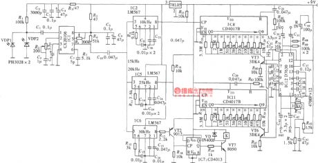
DTMF encoding and decoding six-channel infrared remote controller
Published:2011/8/24 20:51:00 Author:Christina | Keyword: DTMF, encoding, decoding, six-channel, infrared, remote controller
The DTMF encoding and decoding six-channel infrared remote controller is as shown in the figure.
(View)
View full Circuit Diagram | Comments | Reading(3233)
Infrared photoelectric type automatic faucet
Published:2011/8/24 20:58:00 Author:Christina | Keyword: Infrared, photoelectric type, automatic faucet

The Infrared photoelectric type automatic faucet is as shown in the figure.
(View)
View full Circuit Diagram | Comments | Reading(1086)
Electrothermal office desk plate automatic switch circuit
Published:2011/8/24 21:06:00 Author:Christina | Keyword: Electrothermal, office, desk plate, automatic switch

The electrothermal office desk plate automatic switch circuit is as shown in the figure, this device is composed of the ordinary electrothermal office desk plate and the infrared reflected type automatic switch which is composed of the TX05D, it has the automatic electricity heating function when someone is working on the desk, and also it has the function of automatic power off when no one is there. So it can save the electric energy, avoid the frequently plugfest, extend the service life of electrothermal office desk plate and prevent the accidents, it can be used on the ordinary electrothermal office desk plate, it is easy to make and very reliable.
(View)
View full Circuit Diagram | Comments | Reading(734)
AN5521 field scanning output circuit
Published:2011/8/24 21:11:00 Author:Christina | Keyword: field scanning, output circuit


1.Features
The AN5521 is composed of the field scanning pulse forming device, the flyback generator, the driving circuit and the field scanning output circuit, the internal circuit block diagram is as shown in the figure 1-17.
2.Pin functions and data
The AN5521 uses the 7-pin single row DIP package, the pin functions and data are as shown in table 1-17.
(View)
View full Circuit Diagram | Comments | Reading(1244)
Household automatic hand dryer circuit
Published:2011/8/24 21:25:00 Author:Christina | Keyword: Household, automatic, hand dryer

The household automatic hand dryer circuit is as shown in figure (a), it is composed of the infrared reflection switch A1, the AC SSR A2, the hair dryer and the power conversion circuit. After you open the power, the A1 outputs the infrared ray. Because there is no object to reflect the infrared ray, so the OUT port of A1 outputs the low level, the VT cuts off, also the A2, the hair dryer which is connected with the socket XS will not operate. When the hand is below the hand dryer, the infrared ray is reflected by the hand, the OUT port of A1 outputs the high level signal, the VT conducts.
(View)
View full Circuit Diagram | Comments | Reading(5133)
Household automatic faucet composed of the TX05D
Published:2011/8/24 21:39:00 Author:Christina | Keyword: Household, automatic faucet

The Household automatic faucet composed of the TX05D is as shown in the figure.
(View)
View full Circuit Diagram | Comments | Reading(949)
The triangle wave and square wave circuit composed of the analog switch
Published:2011/8/24 21:48:00 Author:Christina | Keyword: triangle wave, square wave, analog switch

The triangle wave and square wave circuit composed of the analog switch is as shown in the figure. In this circuit, the resistance values of the adjustment potentiometer RP2 and RP3 change the reference voltage UR1 and UR2, so we can change the triangular wave voltage level and amplitude accurately and independently. You can change the resistance value of potentiometer RP1 to change the oscillation frequency of the circuit. The UR1 and UR2 can use the external power supply, if it is used with the D/A converter, they can form the digital wave amplitude control triangulation oscillator. If we assume that the stable voltage of VD3 and VD4 is Uz, the oscillation period T=2(RRP1+R1)C1(UR2-UR1)/Uz+0.7), the 0.7(V) is the positive voltage drop of VD3 or VD4.
(View)
View full Circuit Diagram | Comments | Reading(1218)
Automatic counter composed of the TX05D
Published:2011/8/24 21:52:00 Author:Christina | Keyword: Automatic counter

The automatic counter is composed of the TX05D and the pocket calculator. As the figure shows, it can be used in the product automatic counting of the factory production line conveyor belt, the transformer winding circle number automatic counting and the equipment movements automatic counting.
(View)
View full Circuit Diagram | Comments | Reading(770)
The application circuit of the N-type thermocouple
Published:2011/8/23 22:36:00 Author: | Keyword: application circuit, N-type, thermocouple

The thermocouple has the strong durability, the good stability and low price. So it can be used in the industry applications. Figure 3-1 is the application circuit of the N-type thermocouple. It uses the compensation circuit and the digital controlled linear circuit of the chopper-stabilized amplifier △UBE cold contact point. So there is no need to adjust the circuit, in the 4-373K thermodynamics temperature range, the output full-scale error of this circuit is +/-3%. When the circuit is connected with the thermocouple sensor, the circuit will changes into the accurate thermodynamics temperature scale thermometer.
In this circuit, the X9C103 is the digital potentiometer, the HC4053(1)-HC4053(3) are the analog switches, A1 uses the LTC1049 operational amplifier, A2 and A3 use the LTCl541 operational amplifier.
(View)
View full Circuit Diagram | Comments | Reading(2221)
Five-channel audio equipment infrared remote controller (CX20106,NE555, CD4011, CD4017B)
Published:2011/8/23 22:37:00 Author: | Keyword: Five-channel, audio equipment, infrared, remote controller

The D7630 is designed as the application-specific integrated circuit with the DC volume, tone control and balance control functions. It has strong control function, and it can be used as the multi-function control circuit of the double-channel audio power amplifier circuit. In ordinary usage, it uses the manual control mode, and it adjusts the direct voltage through the potentiometer to achieve the purpose of control. This circuit uses the D/A converter circuit to changes the digital circuit output pulse into the direct voltage.
The five-channel infrared remote control signal emitter:
Five channel audio equipment infrared remote controller:
(View)
View full Circuit Diagram | Comments | Reading(3606)
AN5560 50/60Hz identification integrated circuit
Published:2011/8/23 22:37:00 Author: | Keyword: 50/60Hz, identification, integrated circuit

The AN5560 is designed as the 50/60Hz identification integrated circuit that is produced by the Panasonic company, and it can be used in the large-screen multi-system picture in picture color TVs as the field frequency identification device.
1.Features
The AN5560 is composed of the sub-screen horizontal and vertical sync signal processing circuit, the 50/60HZ field frequency identification processing circuit. And this IC uses the single row 7-pin package, the pin function and data are as shwon in table 1-20.
(View)
View full Circuit Diagram | Comments | Reading(801)
Sawtooth wave generator circuit composed of the CD4040
Published:2011/8/23 22:37:00 Author: | Keyword: Sawtooth wave, generator circuit
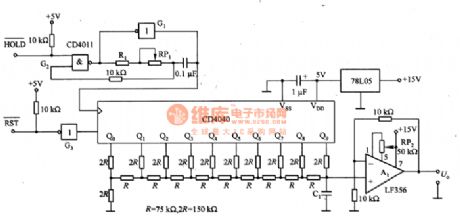
The Sawtooth wave generator circuit composed of the CD4040 is as shown in the figure. This circuit is composed of the clock oscillator, the CD4040 10-bit counter, the R-2R ladder network, the 78L05 reference voltage generator, the A1 buffer amplifier.
The clock oscillator uses the astable multivibrator which is composed of the gate circuit G1, and it can be used in the low frequency oscillation. The CD4040 is the binary counter, you can produce the high precision sawtooth wave by increasing the number of bits. If the VDD terminal voltage of the CD4040 is not stable, the amplitude of the sawtooth wave will change, so we need to use the 78L05 three-port stabilizer to stabilize the voltage.
(View)
View full Circuit Diagram | Comments | Reading(5800)
Four Independent Benchmark Voltage Source Circuit of LMl39
Published:2011/7/26 1:38:00 Author:Michel | Keyword: Benchmark, Voltage Source Circuit


The picture is four independent benchmark voltage source circuit of LMl39.In the circuit,VD1 is used to generate benchmark voltage and comparator LM139 is the adjustable phase amplifier of four independent gains.RP1~RP4 are used to regulate the output voltage and the adjustable range is UZ≤UO≤UCC.In the formula,Uz is voltage regulating voltage of VD1 and R2~R5 are boost resistance of R2~R5 output ends.The current amplification transistor is connected to A1~A4 output ends if the output voltage is increased. (View)
View full Circuit Diagram | Comments | Reading(843)
Voltage-controlled Gain Amplifier(LM307)
Published:2011/8/11 8:15:00 Author:Felicity | Keyword: Voltage-controlled, Gain Amplifier

View full Circuit Diagram | Comments | Reading(1358)
Extremely Wideband High-current Buffer
Published:2011/8/11 8:12:00 Author:Felicity | Keyword: Extremely Wideband, High-current, Buffer

View full Circuit Diagram | Comments | Reading(978)
| Pages:521/2234 At 20521522523524525526527528529530531532533534535536537538539540Under 20 |
Circuit Categories
power supply circuit
Amplifier Circuit
Basic Circuit
LED and Light Circuit
Sensor Circuit
Signal Processing
Electrical Equipment Circuit
Control Circuit
Remote Control Circuit
A/D-D/A Converter Circuit
Audio Circuit
Measuring and Test Circuit
Communication Circuit
Computer-Related Circuit
555 Circuit
Automotive Circuit
Repairing Circuit