
Circuit Diagram
Index 522
12MHz Broadband Buffer Composed Of OPA606
Published:2011/8/11 8:08:00 Author:Felicity | Keyword: 12MHz, Broadband Buffer

View full Circuit Diagram | Comments | Reading(696)
24dB/ octave Low-pass Filter Circuit Composed of the Same Parameters (μPC882)
Published:2011/8/10 9:54:00 Author:Felicity | Keyword: Same Parameters, Low-pass Filter

The circuit is 24dB/ octave low-pass filter composed of the filter components of the same parameters. To get the required Q, the open-loop gain of the operational amplifier should be above 1 and the input stage become a 1/2.57 attenuator. This circuit’s feature is the resistance R and capacitor C with decided cutoff frequency fc can reach the same parameters. The parameters of the circuit are determined by cutoff frequency, fc=1/(2πRC) ,and the resistance range is between several to several hundred kΩ and the capacity is above several hundred pF.
(View)
View full Circuit Diagram | Comments | Reading(2025)
Domestic Time Controller Circuit
Published:2011/8/10 1:41:00 Author:Felicity | Keyword: Domestic, Time Controller
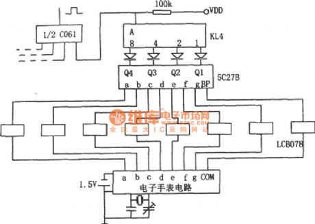
The field signal of the electric watch is voltage rising transformed by interface circuit LCB078 and then put into 5C27B field / BCD decoder. The signal is encoded as binary-decimal BCD code which is compared with the preset time signal consists of swich KL4.When the two are the same , high voltage output by main circuit will make the flip-flop to turn,and the relay drives the related load to work. When they are different , the main circuit output low voltage and the related load will not work.If it need to time several times, Multiple dial switches can be used in parallel connection. (View)
View full Circuit Diagram | Comments | Reading(1188)
308 Integrated Amplifier For High Input Impedance
Published:2011/8/11 7:44:00 Author:Felicity | Keyword: Integrated Amplifier, High Input Impedance

View full Circuit Diagram | Comments | Reading(675)
High-speed Inverting Amplifier(HA5195)
Published:2011/8/11 7:55:00 Author:Felicity | Keyword: High-speed, Inverting Amplifier

View full Circuit Diagram | Comments | Reading(760)
Circuit For Driving A Two-wire Fan (Smart Remote Thermal Fan Controller ADT7460)
Published:2011/8/11 8:04:00 Author:Felicity | Keyword: Two-wire Fan, Smart, Remote, Thermal Fan, Controller

View full Circuit Diagram | Comments | Reading(911)
Agricultural submersible pump anti-theft alarm
Published:2011/8/9 0:05:00 Author:Felicity | Keyword: anti-theft alarm, agricultural submersible pump

When the switch Q turns and the pump havn’t been started,the power transformer T is on.And the induced current produced by the secondary winding goes through the normally open contact of the AC contactor KM, the start-up button,and the stator winding of motor m to form a circuit. And then relay K switches on ,and the normally open contact releases to cut off the power circuit of coil KM and alarm HA. When the line is cut because of the pump being stolen or somehow,the power circuit of relay K will be cut off and its normally close contact closes and HA send alarm. (View)
View full Circuit Diagram | Comments | Reading(3303)
The circuit diagram of a load-driving multiplier (MPY600)
Published:2011/8/9 2:57:00 Author:Felicity | Keyword: load-driving multiplier


The circuit of a load-driving multiplier consists of multiplier MPY600 and high speed cache OPA633 is shown in fig(a). The relationship between input and output : Vo=VxVy/2. The voltage output by high speed cache OPA633 can drive capacitive load.MPY600 is wide bandwith multiplier, and the features are:1 High bandwidth: current output:75MHz, voltage output 30MHz2 Low noises3 Low feedthrough4 The datum output is GND5 Low misalignment voltage.
(View)
View full Circuit Diagram | Comments | Reading(776)
The circuit diagram of high Q notch filter
Published:2011/8/9 3:28:00 Author:Felicity | Keyword: high Q notch filter

This figure shows the circuit of high Q notch filter. The operational amplifier in the low figure comprise voltage follower. The potentiometer R4 can change the value of Q (from 0.3 to 50). And the notch frequency : f0=1/2πR1C1. To avoid the drifting of f0, silvering mica or carbonate capacitor and matallic film resistance are needed. To reach 60dB attenuation, the allowance of resistance is below 0.1% ,and the allowance of capacity is below. To make LM102 work steadily, a 0.01μF capacitor is needed to filter the power. (View)
View full Circuit Diagram | Comments | Reading(1527)
Hum Filter (741) Circuit
Published:2011/8/9 23:25:00 Author:Felicity | Keyword: Hum Filter

The Hum Filter Circuit is showed in the picture. The circuit is an economical narrow-band notch filter. It does not need elements of high accuracy. The frequency can be changed from 50Hz to 60Hz. It is used to eliminate the useless signal and hum in the audio and test instrumentation system. Differential feedback overhead active RC network is used in the circuit. The Notch Bandwidth depends on the feedback value. The Notch Bandwidth is narrow when the feedback value is high. Use the element value in the picture to adjust the potentiometer. It can adjust the frequency to 50Hz or 60Hz. The suppression of hum can reach the value of 30dB. When the frequency is 50Hz the bandwidth is 14Hz. When the frequency is 60Hz the bandwidth is 18Hz. The attenuation of signal is less than 1dB. (View)
View full Circuit Diagram | Comments | Reading(2223)
-18dB/octave Active Low-pass Filter Circuit (RC4558DN)
Published:2011/8/10 7:19:00 Author:Felicity | Keyword: Active, Low-pass Filter


The -18dB/octave active low-pass filter circuit is shown in the figure. This circuit consists of -6dB passive filter and -12dB/octave active filter and the whole circuit is a -18dB/octave active low-pass filter. The passive filter consists of R1 and C3, the active filter consists of R2, R3, C1, C2 and operational amplifier.
(View)
View full Circuit Diagram | Comments | Reading(4197)
Q and Frequency Adjustable Narrow Band Filter (741)
Published:2011/8/10 7:38:00 Author:Felicity | Keyword: Q and Frequency Adjustable, Narrow Band Filter

The circuit is an active Q and frequency adjustable narrow band filter. It adopts the form of Wien bridge positive feedback ,but the loop gain is under 1.The character of this circuit is that adjusting Q has no effect on center frequency, because Q only depends on the gain of the circuit.When the gain is 600,Q is 2000; and when the gain is 140,Q is 30. And in the ordinary Wien bridge oscillator, for non-inverting terminal, the gain of the amplifier must above 3 to oscillate, but in this circuit the gain of the amplifier is below 3. (View)
View full Circuit Diagram | Comments | Reading(1151)
The Circuit of Active High-Pass Filter With Sharp Cutoff Performance (RC4558DN)
Published:2011/8/10 7:58:00 Author:Felicity | Keyword: Active, High-Pass Filter, Sharp Cutoff Performance


Active high-pass filter with sharp cutoff performance is shown in this circuit. To improve the frequency characteristic around cutoff frequency fc of high-pass filter, in this circuit a high-pass filter and a band-stop filter are connected in series to improve the frequency characteristic of the high-pass filter. The first stage in this circuit is band-stop filter consists of double-T network and load resistance R4, composing band-pass filter that gain descends in low frequency. To increase the value of Q, there is a bootstrapping at the end of the double-T network. (View)
View full Circuit Diagram | Comments | Reading(2610)
Wide-range Digital Capacity Measuring Instrument Circuit (NE555, CD4017, MC14553B)
Published:2011/8/10 8:17:00 Author:Felicity | Keyword: Wide-range, Digital, Capacity Measuring Instrument

The pulser is the multivibrator consists of IC1(556) and R1,R2,C1(R3,R4,C2), and the oscillation frequency is 1.44/(R1+2R2)C1,or f2=1.44/(R3+2R4)C2. The advancing edge of the pulse output by pin 9 make the output terminal of D flip-flop IC2(CD4013) generate low voltage that put on the enable terminal (EN terminal) of the counter IC4(CD4071) to make it count. The pulse output by pin 5 control the DIS terminal of the 3 bit BCD counting circuit IC5 (MC14553B) The test capacitor capacity-frequency transform circuit consists of R7, R8, and IC3 (555) and the test capacitor Cx. It transforms the capacity of Cx into oscillation pulse pending to test as the counting clock onto IC4. (View)
View full Circuit Diagram | Comments | Reading(4765)
Single-peak Filter Circuit Composed of One Operational Amplifier
Published:2011/8/10 8:35:00 Author:Felicity | Keyword: Single-peak Filter, Operational Amplifier


The single-peak filter composed of one operational amplifier is shown in the figure. This circuit only uses one operational amplifier and a few components to build up filter circuit that has the same performance composed of LC components. The resonant frequency can be easily tuned without changing the circuit gain. This circuit uses potentiometer PR1 to tune the resonant frequency. When the value of PR1 varies from minimum to maximum, the resonant frequency tuned range is 1580Hz, and the circuit gain hardly changes. (View)
View full Circuit Diagram | Comments | Reading(1199)
The blind source device (μA741, LM567 and KD153) (2)
Published:2011/8/13 2:16:00 Author:qqtang | Keyword: blind source device

View full Circuit Diagram | Comments | Reading(773)
The blind source device (LM567 and KD56022) (1)
Published:2011/8/13 2:24:00 Author:qqtang | Keyword: blind source device

The blind always takes a stick to help them avoid obstacles when they are out of homes. As the stick can't be too long, the distance is limited. By installing a micro ultrasonic probe in the stick, not only the probing efficiency and distance can be raised, but also it's convenient to use. In the figure is the blind source device of ultrasonic probe, whose circuit is shown there. The circuit consists of the ultrasonic emitter, ultrasonic receiver and signal voltage amplifier, ultrasonic detection circuit and alarm sound circuit. (View)
View full Circuit Diagram | Comments | Reading(1802)
AN366,AN366P AM frequency conversion, FM AM intermediate frequency amplifier integrated circuit
Published:2011/8/25 20:11:00 Author:TaoXi | Keyword: AM, frequency conversion, FM, intermediate frequency, amplifier, integrated circuit


The AN366 and AN366P are designed as the AM frequency conversion, FM AM intermediate frequency amplifier integrated circuit that is produced by the Panasonic company, and this device can be used in the radio and home stereo system. The two kinds of IC have the same functions, the difference between them is the electric parameters.
1.The internal circuit block diagram and pin functions of the AN366P
The AN366P has the FM system and the AM system, the FM and AM intermediate frequency amplifier can be connected with the ceramic filter; the detection-wave output levels of the FM and AM are the same. This IC uses the dual-row DIP package, the internal circuit block diagram is as shown in figure 1-12, the pin functions and data are as shown in table 1-1.
(View)
View full Circuit Diagram | Comments | Reading(2216)
Overcurrent latch circuit composed of the M51958B
Published:2011/8/25 20:29:00 Author:TaoXi | Keyword: Overcurrent, latch circuit

The overcurrent latch circuit is composed of the M51958B. Because the power supply is the multi-output power, if anyone of the channels is in the overcurrent protection state, the voltage will decrease, the optocoupler TLP521 cuts off, the side control PWM integrated circuit stops working, the power supply is protected. This circuit controls all of the PWM integrated circuits, and it has the overvoltage protection locking terminal. The R1-R5 are the dividing resistors, the set voltage of the midpoints is higher than the pin-2 peak voltage of the M51958B (10%-20%). The R1 and C2 decide the start time constant of the circuit, R6 is the dark current resistance of the TLP521 that can be used to prevent the optocoupler error action.
(View)
View full Circuit Diagram | Comments | Reading(1350)
Household electric fan infrared remote controller (NE555, CD4017, CD4066)
Published:2011/8/25 20:40:00 Author:TaoXi | Keyword: Household, electric fan, infrared, remote controller
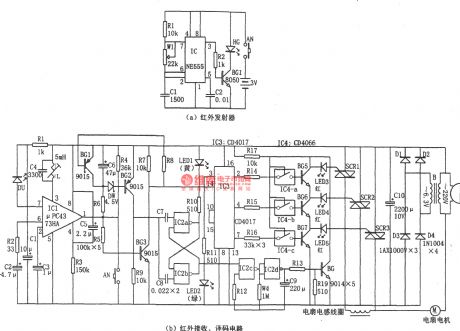
The household electric fan infrared remote controller is as shown in the figure. This remote controller has the emitter and the receiving, control parts. The infrared transmitter is designed as the astable multivibrator which is composed of the 555 and R1, W1, C1, the oscillation frequency f=1.44/(R1+2Rw1)C1, the oscillation frequency is 38kHz to drive the infrared emission diode HG310 or HG450 to output the infrared pulse. The infrared receiving tube need to use the corresponding tube, and you need to notice the optical wavelength and optical power. The IC1 uses the special infrared receiver manifold μPC1373HA.
(View)
View full Circuit Diagram | Comments | Reading(2499)
| Pages:522/2234 At 20521522523524525526527528529530531532533534535536537538539540Under 20 |
Circuit Categories
power supply circuit
Amplifier Circuit
Basic Circuit
LED and Light Circuit
Sensor Circuit
Signal Processing
Electrical Equipment Circuit
Control Circuit
Remote Control Circuit
A/D-D/A Converter Circuit
Audio Circuit
Measuring and Test Circuit
Communication Circuit
Computer-Related Circuit
555 Circuit
Automotive Circuit
Repairing Circuit