
Circuit Diagram
Index 524
Electric fan infrared remote control circuit (KD880/881)
Published:2011/8/25 21:52:00 Author:TaoXi | Keyword: Electric fan, infrared, remote control circuit
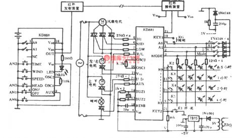
The Electric fan infrared remote control circuit (KD880/881) is as shown in the figure.
(View)
View full Circuit Diagram | Comments | Reading(2162)
Electromotor constant speed control circuit composed of the CA0358
Published:2011/8/25 22:03:00 Author:TaoXi | Keyword: Electromotor, constant speed, control circuit

The Electromotor constant speed control circuit composed of the CA0358 is as shown in the figure. In the circuit, the differential amplifier A2 detects the ends voltage Um of the electromotor, A2 adds the output voltage Um to the inverting input port of the differential amplifier A3. At the same time, the A1 detects the ends voltage of Rm/10 (Rm is the DC resistance of the electromotor armature) UR, and it amplifies the voltage to 10 times. The voltage adds to the in-phase input port of A3. RP4 can be used to adjust the magnification of A1. You need to make the electromotor break away from the power circuit and make it stop working, you can adjust the RP4 until the A3's output is zero.
(View)
View full Circuit Diagram | Comments | Reading(1342)
The instrument amplifier with floating signal source composed of INA110
Published:2011/8/13 3:08:00 Author:qqtang | Keyword: instrument amplifier, floating signal source

View full Circuit Diagram | Comments | Reading(687)
The capacitance phase-distribution single-phase motor connection circuit and phasor diagram
Published:2011/8/23 22:38:00 Author:qqtang | Keyword: phase-distribution, single-phase motor, connection circuit

To generate a rotating field, the phase is distributed by using the serial capacitor in the starting coil, the wiring principle is shown in Figure 5.2(a). As long as the proper parameters are chosen, the phase difference between the working coil and starting coil is 90°, see as figure 5.2(b), the phase-distributed wave shape is shown in figure 5.3.
(View)
View full Circuit Diagram | Comments | Reading(995)
The data collecting system circuit (ADC0840)
Published:2011/8/13 2:04:00 Author:qqtang | Keyword: data collecting system

View full Circuit Diagram | Comments | Reading(632)
The micro-computer data collecting system circuit(AD7501, AD582 and AD1408)
Published:2011/8/23 22:38:00 Author:qqtang | Keyword: micro-computer, data collecting system

The micro-computer data collecting system circuit composed of AD570, AD1408 and micro-processor CPU8155 is shown in the figure. The circuit under test has 8 channels, each channel is tested in sequence, the scanning of each channel is not more than 50μs, the system logic LEV is TTL, binary system code, the data transmission is parallel.
(View)
View full Circuit Diagram | Comments | Reading(899)
Electric fan infrared remote control circuit (Greatwall FS22-40)
Published:2011/8/25 22:07:00 Author:TaoXi | Keyword: Electric fan, infrared, remote control, Greatwall

Electric fan infrared remote control circuit (Greatwall FS22-40)
The emitter:
The receiver:
(View)
View full Circuit Diagram | Comments | Reading(1390)
The intelligent digital voltmeter composed of HI7159A and 8031 single chip machine
Published:2011/8/23 22:39:00 Author:qqtang | Keyword: digital voltmeter, single chip machine

The intelligent digital voltmeter composed of HI7159A and 8031 single chip machine is shown in the figure. The circuit is equipped with gradual accumulation integration, digital zero set, low noise BIMOS and other technologies. The maximum counting value is 199999 under the working mode of 5 1/2, its precision is ±0.005%. (View)
View full Circuit Diagram | Comments | Reading(1349)
Ramp function generator circuit composed of the TA7507
Published:2011/8/25 22:23:00 Author:TaoXi | Keyword: Ramp, function, generator
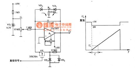
The ramp function generator circuit composed of the TA7507 is as shown in the figure. This circuit is designed as one kind of Mueller integral circuit, and it changes into the ramp function generator circuit by adding some related components. In this circuit, the VT1 is the N channel MOSFET tube (0V cut-off and +5V conduction), the vd4 and vd5 clamp the drain voltage of VT1 at 0V. When the output voltage increases, it can prevent the VT1 to be damaged.
When the VT1 is in the cut-off state, the A1 integrates the input benchmark voltage U, so the circuit outputs the ramp waveform. In the circuit, A1 uses the A7507, it is one kind of FET input type operational amplifier.
(View)
View full Circuit Diagram | Comments | Reading(2438)
The single machine reset circuit
Published:2011/8/23 22:39:00 Author:qqtang | Keyword: single machine, reset circuit


Figure 2 by increasing the RC reset circuit of the discharging circuit and using the comparator circuit, it can not only solve the problem of the system instability caused by the power supply burr, but also the power supply will fall down or reset reliably. Figure 4 is an practical example, when VCC x (R1/(R1+R2) ) =0.7V, Q1 is blocked and the system is reset. The amplifying function of Q1 can also improve the loading character of the circuit, but its obvious defect is that hop sill voltage Vt is affected by VCC, but the use of diode can avoid this problem.
Figure 3 the input-output feature of RC reset circuit
(View)
View full Circuit Diagram | Comments | Reading(1017)
Pulse width modulation circuit composed of the μA741
Published:2011/8/25 22:31:00 Author:TaoXi | Keyword: Pulse width, modulation circuit

The pulse width modulation circuit composed of the μA741 is as shown in the figure. In this circuit, the A1 is the integral circuit, A2 is the comparator circuit; A3 is the reference voltage generating circuit. The operating principle: when the Ui=O, the Ur is the reference voltage, it is +/-5V. We suppose that the Ur=-5V, the comparation circuit of the inverting input port is UQ=-2.5V, the positive linearity of the integrator A1's output voltage Ua will increase. When the Ua is +2.5V, A2 outputs the reversal, S1 connects, the reference voltage Ur is +5V, the comparation voltage UQ is +2.5V. So A1 starts the backward integration process.
(View)
View full Circuit Diagram | Comments | Reading(1054)
Electric fan infrared remote control circuit (Greatwall FS26-40)
Published:2011/8/25 22:12:00 Author:TaoXi | Keyword: Electric fan, infrared, remote control, Greatwall
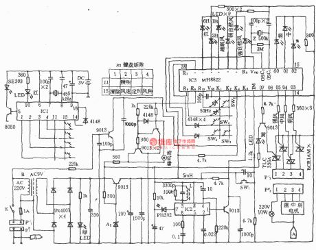
Electric fan infrared remote control circuit (Greatwall FS26-40)
(View)
View full Circuit Diagram | Comments | Reading(2542)
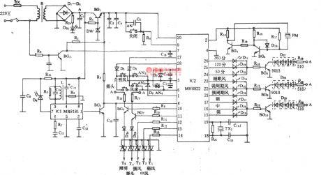
Remote control multi-file controller
Published:2011/8/25 22:42:00 Author:TaoXi | Keyword: Remote control, multi-file, controller

The remote control multi-file controller is as shown in the figure. This circuit has the radio transmitter and the wireless receiving and controller parts. The generator is the self-excited multivibrator circuit. The oscillation frequency f=l.44/(R1C2+R2C3). The controller uses the 30~40MHz amateur frequency range. The frequency selection circuit of the receiver outputs the high-frequency signal, and this signal is rectified by D1 and D2, and it also amplified by BG3 to be sent to the pin-1 of IC1. The IC1 uses the BH-SK-V type integrated package, it has the level 2 high power gain amplifier, the frequency selector, the plastic device and the trigger, driver.
(View)
View full Circuit Diagram | Comments | Reading(635)
Electromotor servo amplifier composed of the power MOSFET
Published:2011/8/26 0:50:00 Author:TaoXi | Keyword: Electromotor, servo amplifier, power MOSFET

The electromotor servo amplifier composed of the power MOSFET is as shown in the figure. The MOSFET grid electrode driving boost circuit is composed of the G1-G3, the oscillation frequency is 20KHz, it is decided by the R1 and C1. The benchmark pulse generating circuit is composed of the G4 and G5, the RP1 can be used to adjust the midpoint voltage, the Ui is the output control siganl; the pulse width comparison circuit is composed of G7 and G8; the pulse stretcher circuit is composed of G9 and G10; the MOSFET grid electrode excitation circuit is composed of the VTl, VT2, VT7 and VT8, the electromotor driving circuit is composed of VT3-VT6.
(View)
View full Circuit Diagram | Comments | Reading(2162)
The development of the linear matrix CCD test system based on the single chip machine
Published:2011/8/23 22:39:00 Author:qqtang | Keyword: linear matrix, CCD test system, single chip machine

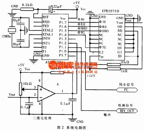

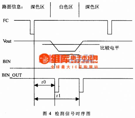
Let's assume to set a white line(the width is 300mm) on a plate of deep color (e.g black, blue and green, etc) as the moving track outgoing line of the robot, the test system of the white track is developed by using the linear matrix CCD. We first image the road information on the CCD sensitivesurface by using the optical system camera; and then the white line position is read out as the vision sense of the robot which is controlled to move along the white line. This is a typical CCD time test system.
(View)
View full Circuit Diagram | Comments | Reading(1178)
The power failure protection circuit of the single chip system
Published:2011/8/23 22:39:00 Author:qqtang | Keyword: power failure, protection circuit, single chip system

When the main power is normal, the signal chip machine is powered by VCC5V, at the moment, the VCC5V power supply is charging the battery through D1 and R1, by which the fullness of the battery volume can be ensured. If the right resistor R1 is chosen, then the charging current and charge time will be proper. For example, when charging 3V6 * 60mAH battery, the charge time is about 8h, then we choose the charge current as 8mA, R1=(6V-0.6)/8(0.6 is the conducting step-down of the serial diode). (View)
View full Circuit Diagram | Comments | Reading(638)
Decorative light controller composed of the Y977A/B
Published:2011/8/26 3:29:00 Author:TaoXi | Keyword: Decorative light, controller

View full Circuit Diagram | Comments | Reading(880)
The automatic flush device circuit
Published:2011/8/13 2:05:00 Author:qqtang | Keyword: automatic flush device

View full Circuit Diagram | Comments | Reading(1122)
The glowing display logic pen composed of NE555 circuit
Published:2011/8/13 2:08:00 Author:qqtang | Keyword: display logic pen, NE555

View full Circuit Diagram | Comments | Reading(854)
Zero-cross driving circuit
Published:2011/8/26 1:37:00 Author:TaoXi | Keyword: Zero-cross, driving circuit

The zero-crossing driving circuit is as shown in the figure. The zero-crossing driver means the circuit can control the on/off of the current at the AC voltage zero-crossing point to reduce the switching surge amd the electromagnetic interference. In the circuit, the ZNR is the sensitive component which can be used to absorb the surge to protect the power components.
(View)
View full Circuit Diagram | Comments | Reading(892)
| Pages:524/2234 At 20521522523524525526527528529530531532533534535536537538539540Under 20 |
Circuit Categories
power supply circuit
Amplifier Circuit
Basic Circuit
LED and Light Circuit
Sensor Circuit
Signal Processing
Electrical Equipment Circuit
Control Circuit
Remote Control Circuit
A/D-D/A Converter Circuit
Audio Circuit
Measuring and Test Circuit
Communication Circuit
Computer-Related Circuit
555 Circuit
Automotive Circuit
Repairing Circuit