
Circuit Diagram
Index 528
The multi-meter with additional field intensity meter circuit
Published:2011/8/13 1:14:00 Author:qqtang | Keyword: multi-meter, field intensity meter

View full Circuit Diagram | Comments | Reading(970)
The PVDF heart sounds impulse measuring circuit
Published:2011/8/14 22:19:00 Author:qqtang | Keyword: PVDF, heart sounds, impulse measuring circuit
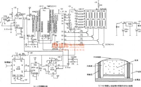
In the figure is the PVD heart sounds impulse measuring circuit. The circuit consists of the single steady oscillator(4538), frequency distributor (4024), pulse generator(ICM7555), counter (4040), storage(ROM), 7-stage lock storage drive(7511),7-stage digital LED and so on. In figure (a) is the PVDF heart sounds impulse sensor structure circuit. For figure (a), PVDF film is a dome shell and it sticks out, so it can contact the earth well. As the PVDF material is soft, which can cling to the skin, its impedance can couple with the skin. (View)
View full Circuit Diagram | Comments | Reading(1464)
The transistor character curve plotter composed of 555
Published:2011/8/14 22:29:00 Author:qqtang | Keyword: transistor character, curve plotter

In the figure is the transistor character curve plotter composed of 555. See as figure (a), the circuit consists of the sawtooth wave generator and step wave generator. As it needs two voltages to draw the transistor character, one is the step wave on the b pole, which generates different base currents lb; the other is the sawtooth wave on the c pole, whose period is corresponding to the step wave, so the output character curve of the transistor can be drawn out, i.e Ic-Vce character curve. The sawtooth generator consists of the oscillator (IC(555), R1, R2 and C1) and integral circuit (C2 and R3). (View)
View full Circuit Diagram | Comments | Reading(966)
The classical power supply circuit (7805 expanded current)
Published:2011/8/13 1:15:00 Author:qqtang | Keyword: power supply, expanded current

View full Circuit Diagram | Comments | Reading(2348)
The capacitor (higher than 100pF) selecting circuit
Published:2011/8/13 1:16:00 Author:qqtang | Keyword: capacitor, selecting circuit

View full Circuit Diagram | Comments | Reading(802)
The application circuit of the single chip wide frequency band phase difference test system AD8302
Published:2011/8/14 22:38:00 Author:qqtang | Keyword: application circuit, single chip, phase difference, test system

The AD8302 application circuit is shown in the figure. R1 and R2 are the input terminals. R3 is the load of the UREF output terminal. C1 and C4 are the AC input coupling capacitor, C2 and C3 are the filtering capacitors, C5 and C6 are the power supply decoupling capacitors. S1 is the gain test pattern/comparator pattern selecting switch, by pulling S2 to gear a, the phase difference test pattern; when it is pulled to gear b, the comparator pattern is chosen, PSET terminal sets the voltage. (View)
View full Circuit Diagram | Comments | Reading(952)
The microampere meter internal resistance test circuit
Published:2011/8/13 1:18:00 Author:qqtang | Keyword: microampere meter, internal resistance, test circuit

View full Circuit Diagram | Comments | Reading(1342)
The power supply internal resistance measuring circuit
Published:2011/8/13 1:20:00 Author:qqtang | Keyword: power supply, internal resistance, measuring circuit

View full Circuit Diagram | Comments | Reading(799)
The single knot transistor speed test circuit (1)
Published:2011/8/13 1:21:00 Author:qqtang | Keyword: single knot, transistor speed test circuit

View full Circuit Diagram | Comments | Reading(1102)
The electric mosquito dispeller
Published:2011/8/23 22:36:00 Author:qqtang | Keyword: mosquito dispeller
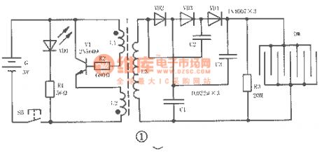
The electric mosquito dispeller circuit is shown in figure 1, which consists of the high frequency oscillator circuit, triple voltage rectifier circuit and high voltage shock net DW.
When the power supply switch SB is pressed, the high frequency oscillator, which consists of the triode VT and transformer T, is getting power and working, it switches the 3V DC into the 18kHz high frequency AC, then it is boosted to about 500V(which is got from the 2 terminals of L3) by T, and then it is boosted to 1500V by the diodes VD2~VD4 and capacitors C1~C3, the boosted voltage is added on the metal net DW. (View)
View full Circuit Diagram | Comments | Reading(3817)
The 3 working pattens of the single chip frequency phase difference test system of AD8302
Published:2011/8/13 1:29:00 Author:qqtang | Keyword: working pattens, single chip, phase difference, test system


The test patten basic connection circuit of the single chip wide frequency band phase difference test system of AD8302:
Comparator patten connection circuit:
Control patten connection circuit:
(View)
View full Circuit Diagram | Comments | Reading(1195)
The regulator: DC-DC circuit, power supply monitor pin and its main features LM2984C
Published:2011/8/23 22:24:00 Author:Seven | Keyword: DC-DC circuit, power supply, monitor pin

LM2984C--the multi-line output stabilizer (with reset terminal) This is a multi-line output stabilizer with fixed output voltage; it has main output, buffering output and affiliated output of tracking type; its main output voltage is 5V and current is 500mA; when the output current is 500mA, the minimum input-output voltage difference is lower than 0.8V; the buffering output voltage is 5V, output current is 100mA; when the output current is 100mA, the minimum input-output voltage is lower than 0.5V; the affiliated ouput-input voltage gap is 5V, output current is 7.5mA.
(View)
View full Circuit Diagram | Comments | Reading(552)
The regulator: DC-DC circuit, power supply monitor pin and its main features M5172L
Published:2011/8/28 3:13:00 Author:Seven | Keyword: DC-DC circuit, power supply, monitor pin

(View)
View full Circuit Diagram | Comments | Reading(704)
The regulator: DC-DC circuit, power supply monitor pin and its main features LP2950/2951
Published:2011/8/23 22:26:00 Author:Seven | Keyword: DC-DC circuit, power supply, monitor pin

LP2950/2951 the high-precision stabilizer LP2950 is a 5V output 3-terminal regulator, LP2951 is a adjustable regulator whose output voltage range is 1.24~29V; the output current is 100mA; output voltage fault typical value is ±0.5%; load stability and linear stability typical value is 0.05%; when the output current is 100mA, the minimum input-output voltage difference typical value is 380mV; input voltage range is -0.3~+30V; it contains the current limitation and over-heat limitation circuit.
(View)
View full Circuit Diagram | Comments | Reading(694)
The random system output circuit composed of CD4017 (1)
Published:2011/8/12 10:43:00 Author:qqtang | Keyword: random system, output circuit

View full Circuit Diagram | Comments | Reading(1017)
The multi-system counter composed of CD4017 and selective switch
Published:2011/8/13 0:29:00 Author:qqtang | Keyword: multi-system counter, selective switch

View full Circuit Diagram | Comments | Reading(1115)
The absolutely available A4 switch power supply: Hitachi AIPM8C power supply (A4)
Published:2011/8/13 0:46:00 Author:qqtang | Keyword: switch power supply, Hitachi

View full Circuit Diagram | Comments | Reading(664)
The binary-coded decimal counter composed of CD4017
Published:2011/8/13 0:57:00 Author:qqtang | Keyword: binary-coded decimal, counter

In the figure is a binary-coded decimal counter composed of 2 CD4017, one CD4066 and one CD4013, of which IC3 and IC4 are the counter, IC2 is used to connect the working power supply and counting pulse input circuit of IC3 and IC4, IC1 is used to control them. C1 and R2 compose the reset circuit of IC3 and the offset circuit of IC1. C2 and R3 compose the reset circuit of IC4. VD1 and VD2 are the divide diodes of the counter switch control circuit. (View)
View full Circuit Diagram | Comments | Reading(1150)
The 1~17 system counter composed of CD4017 (2)
Published:2011/8/13 0:59:00 Author:qqtang | Keyword: counter, system

View full Circuit Diagram | Comments | Reading(686)
The principle diagram of the +60V circuit
Published:2011/8/13 1:00:00 Author:qqtang | Keyword: principle diagram, +60V

View full Circuit Diagram | Comments | Reading(852)
| Pages:528/2234 At 20521522523524525526527528529530531532533534535536537538539540Under 20 |
Circuit Categories
power supply circuit
Amplifier Circuit
Basic Circuit
LED and Light Circuit
Sensor Circuit
Signal Processing
Electrical Equipment Circuit
Control Circuit
Remote Control Circuit
A/D-D/A Converter Circuit
Audio Circuit
Measuring and Test Circuit
Communication Circuit
Computer-Related Circuit
555 Circuit
Automotive Circuit
Repairing Circuit