
Circuit Diagram
Index 531
The regulator: DC-DC circuit, power supply monitor pin and its main features DS1259
Published:2011/8/29 2:23:00 Author:Seven | Keyword: DC-DC circuit, power supply, monitor pin

Working voltage is 5.0V; the power supply fault signal can halt the processor, which can also fulfill the storage protection; the cell current is lower than 100nA; cell low-voltage alarm. The definitions of its main pins: VBAT: cell input; BF:cell fault output signal; BAT: the cell output; PF:power supply fault output signal. VCC0: RAM power supply voltage. (View)
View full Circuit Diagram | Comments | Reading(519)
The regulator: DC-DC circuit, power supply monitor pin and its main features DS1238A
Published:2011/8/28 1:06:00 Author:Seven | Keyword: DC-DC circuit, power supply, monitor pin

DS1238A--the power supply managerThe working voltage is 5.0V; the working temperature range is -40~85℃; it has a halt and restart malfunction microprocessor; it can forecast the alarm when the danger is coming; it can convert SRAM into the non-easy losing storage, when the power supply fault is out the range, it will fulfill read and write protection non-conditionally; the cell current is lower than 200nA; it resets without shaking keys; the monitor precision is 10%Vcc; the DS1238-5 monitor precision is 5%Vcc; it can replace MAX691 directly.
(View)
View full Circuit Diagram | Comments | Reading(546)
The regulator: DC-DC circuit, power supply monitor pin and its main features DS1236
Published:2011/8/25 5:14:00 Author:Seven | Keyword: DC-DC circuit, power supply, monitor pin

The DS1236 power supply controllerThe working voltage is 5.0V; the working temperature range is -40~85℃; it can halt or restart the malfunctioning microprocessor; it can be used in external overload key monitoring; when the power supply fault is approaching, it will send the forecast to the processor; it converts static RAM into non-easy-lost storage; when the power supply voltage fault is too large, it will fulfill writing protection unconditionally; the cell current is lower than 100nA; the monitor precision is 10%Vcc, the monitor precision of DS1236-5 is 5%/Vcc. The main pins are as follows:VBAT: the +3 battery voltage input; VCC0: the switch SRAM power supply output.
(View)
View full Circuit Diagram | Comments | Reading(546)
The regulator: DC-DC circuit, power supply monitor pin and its main features CW1524/2524/3524
Published:2011/8/25 4:22:00 Author:Seven | Keyword: DC-DC circuit, power supply, monitor pin
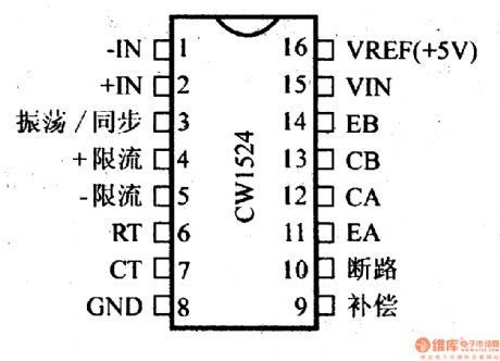
CW1524/2524/3524--the switch stabilizer control circuitThis is a switch stabilizer control circuit which contains the fault amplifier, oscillator, 5V reference circuit, PWM, pulse trigger, 2 crossing output switch tube; the max input voltage is 40V; the output current is 100mA; the working frequency is adjustable, which can be higher than 100kHz; the effect on the frequency stability from temperature is lower than 2%; the output switch tube can be used in a couple or singularity; the power consumption is 1W; it contains the power limitation circuit and over-current protection circuit.
(View)
View full Circuit Diagram | Comments | Reading(1089)
The regulator: DC-DC circuit, power supply monitor pin and its main features DS1232LP/LPS
Published:2011/8/25 5:04:00 Author:Seven | Keyword: DC-DC circuit, power supply, monitor pin
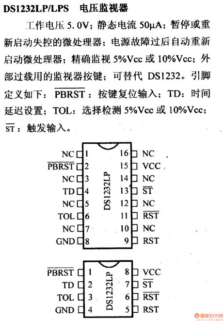
The DS1232LP/LPS voltage monitorThe working voltage is 5.0V; the static current is 50μA; it can halt or restart the malfunctioning microprocessor; it can restart the microprocessor after the power failure; the monitor precision is 5%Vcc or 10%Vcc; it has a monitor key of external overload; it can replace DS1232. The definition of the pins are as follows: : key reset input; TD: time delay setting; TOL: choosing detection of 5%Vcc or 10%Vcc; : the trigger input.
(View)
View full Circuit Diagram | Comments | Reading(628)
The regulator: DC-DC circuit, power supply monitor pin and its main features CW79M00
Published:2011/8/25 4:41:00 Author:Seven | Keyword: DC-DC circuit, power supply, monitor pin
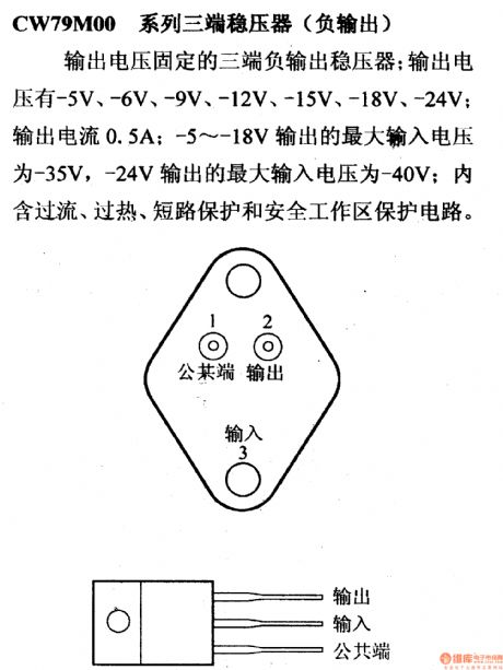
The CW79M00 3-terminal stabilizer (negative output)This is a 3-terminal negative output stabilizer with fixed output voltage; the output voltage can be -5V, -6V, -9V, -12V, -15V, -18V and -24V; the output current is 0.5A; the MAX input voltage of -5~-18V output voltage is -35V, the MAX input voltage of -24V output voltage is -40V; the contains the over-current, over-heat, short-circuit protection and secure working area protection circuit.
(View)
View full Circuit Diagram | Comments | Reading(977)
Color monitor switching power supply (TEAl504) circuit diagram
Published:2011/8/24 22:02:00 Author:Ecco | Keyword: Color monitor , switching power supply

View full Circuit Diagram | Comments | Reading(1087)
Color monitor switching power supply (KA2S0880) circuit diagram
Published:2011/8/24 22:02:00 Author:Ecco | Keyword: Color monitor , switching power supply

View full Circuit Diagram | Comments | Reading(3182)
Differential filter circuit diagram
Published:2011/8/24 22:01:00 Author:Ecco | Keyword: Differential filter

View full Circuit Diagram | Comments | Reading(729)
Optical electronic doorbell 2
Published:2011/8/11 21:05:00 Author:Ecco | Keyword: Optical electronic doorbell
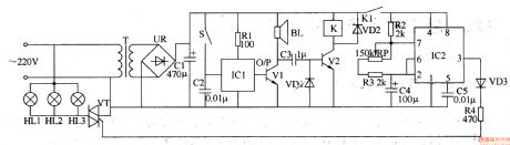
The optical electronic doorbell circuit is composed of the power supply circuit, oscillator circuit, music generating circuit and color bulb control circuit and other components, and it is shown in Figure 3-112. Power supply circuit consists of the power transformer T, bridge rectifier UR and filter capacitor CI. Oscillator circuit consists of the time-base integrated circuit IC2 and external RC components. Music generating circuit consists of the button S, music integrated circuit ICl, transistor Vl, speaker BL and resistor Rl, capacitor C2 and so on. Color bulb control circuit consists of lantern lights HL1-HL3, two-way thyristor VT, transistor V2 and relay K and other components. Rl-R4 select the 1/4W or 1/8W carbon film resistors.
(View)
View full Circuit Diagram | Comments | Reading(1112)
Once timer controller 5
Published:2011/8/8 21:10:00 Author:Ecco | Keyword: Once timer controller

The once timer controller circuit is composed of the power supply circuit and timing control circuit, and it is shown in Figure 3-87. Power supply circuit is composed of the power switch Sl, fuse FU, power transformer T, rectifier diodes VDl-VD4, filter capacitors C4, C5, and three-terminal voltage regulator integrated circuit ICl. Timing control circuit is composed of the time-base circuits IC2, 1C3, resistors Rl-RlO, capacitors Cl-C3, potentiometers RPl, RP2, transistors Vl-V4, light-emitting diodes VLl, VL2, diode VD5, manual discharge button S2, function selector switch S3 and the relay K.
(View)
View full Circuit Diagram | Comments | Reading(874)
Light-operated moth-killing lamp
Published:2011/8/11 20:53:00 Author:Ecco | Keyword: Light-operated , moth-killing lamp

The light-operated moth-killing lamp circuit is composed of the Triac VT, two-way trigger diode V, photosensitive resistor RG, resistor R, capacitor C, and EL lamp, and it is shown in Figure 4-43. In the daytime, RG is the low resistance state (less than 5kΩ) which is affected by light exposure, and C can not be charged as being shorted by RG, V and VT can not turn on, EL does not shine. In the night, RG is in high-impedance state (greater than 1MΩ) and oc is charged normally, KL lit. R select the lW metal film resistor. RG chooses MG45 series of photosensitive resistor. V selects the DB3 or 2CTS2 two-way trigger diode.
(View)
View full Circuit Diagram | Comments | Reading(1243)
Brood thermostat
Published:2011/8/10 3:48:00 Author:Ecco | Keyword: Brood thermostat

The brood thermostat circuit is composed of the power supply circuit and temperature detection control circuit, and it is shown in Figure 4-41. Power supply circuit is composed of the power transformer T, bridge rectifier UR, filter capacitors Cl, C2, and three-terminal voltage regulator integrated circuit ICl. Temperature detection control circuit consists of transistors Vl, V2, resistors Rl-R3, potentiometer RP, capacitor C3, diode VD, operational amplifier integrated circuit IC2, heater EH and relay K. Rl-R3 use 1/4W metal film resistors or carbon film resistors. C3 uses the monolithic capacitor or polyester capacitor.
(View)
View full Circuit Diagram | Comments | Reading(1250)
Fish hatching pool controller 2
Published:2011/8/10 3:44:00 Author:Ecco | Keyword: Fish hatching pool controller

The fish hatching controller circuit is composed of the power supply circuit, time control circuit, working status indication circuit and control implementation of circuit, and it is shown in Figure 4-25. The power supply circuit consists of the step-down capacitor C8, resistors Rl2, R13, rectifier diodes VDl-VD4, three-terminal integrated voltage regulator IC3, and filter capacitors C6, C7 and so on. Time control circuit is composed of the quench time control circuit switch Sl, resistors R14-R19, Rl-R4, time-base integrated circuit IC1 and capacitors Cl, C2 and so on. Rl-Rll and R14-Rl9 select the 1/4W carbon film resistors.
(View)
View full Circuit Diagram | Comments | Reading(703)
Fish hatching pool controller 1
Published:2011/8/10 3:41:00 Author:Ecco | Keyword: Fish hatching pool, controller

The fish hatching controller circuit is composed of the power supply circuit, oxygen pump automatic control circuit and water temperature automatic control circuit, and it is shown in Figure 4-24. Power supply circuit is composed of the power switch Sl, power transformer T, rectifier diodes VDl-VD4, three-terminal regulator ICl and filter capacitors Cl, C2 and so on. Oxygen pump automatic control circuit consists of the oxygen pump motor M, selector switch S2, relay Kl, driver transistor Vl, and the time-base integrated circuit IC2a and external RC components. Automatic temperature control circuit is composed of the electric heater EH, relay K2, drive transistor V2, time-base integrated circuit IC2b, the electric contact thermometer Q and external RC components.
(View)
View full Circuit Diagram | Comments | Reading(1112)
Fish farming thermostat controller 2
Published:2011/8/8 21:52:00 Author:Ecco | Keyword: Fish farming, thermostat controller

The fish farming thermostat controller circuit is composed of the power supply circuit and temperature detection control circuit, and it is shown in Figure 4-23. Power supply circuit is composed of the power transformer T, rectifier diodes VD2, VD3, filter capacitor C2, limiting resistor R3 and power indicator LED VLl. Temperature detection control circuit consists of the thermistor RT, resistors Rl, R2, capacitor Cl, potentiometer RP, time-base integrated circuit IC, heating working indicating light-emitting diode Vm, relay K and diode VDl. Rl-R3 use 1/4W metal film resistors or carbon film resistors.
(View)
View full Circuit Diagram | Comments | Reading(1974)
Fish farming thermostat controller 1
Published:2011/8/8 21:48:00 Author:Ecco | Keyword: Fish farming , thermostat controller

The fish farming thermostat controller circuit is composed of the power supply circuit and temperature control circuit, and it is shown in Figure 4-22. Power supply circuit consists of the power switch S, power transformer T, electric heater EH and rectifier diodes VDI-VD4. Temperature control circuit consists of the resistors Rl-R3, thermistor RT, potentiometer RP, capacitor C, single-junction transistor VU and thyristor VT. Rl select the 1/2W metal film resistor; R2 and R3 select the 1/4W metal film resistors or carbon film resistors. RP chooses the solid synthetic membrane potential potentiometer. C uses the monolithic capacitor or polyester capacitor.
(View)
View full Circuit Diagram | Comments | Reading(862)
Sound, light dual control delay light circuit diagram 1
Published:2011/8/22 3:16:00 Author:Ecco | Keyword: Sound , light , dual control , delay light

The sound, light dual control delay light circuit is composed of the power supply circuit, voice circuit, light control circuit and time delay control switch circuit, and it is shown as below. In the circuit, power supply circuit is composed of the light EL, diodes VD1-VD5, resistor R1, capacitor C1 and Zener diode VS; voice circuit is composed of the microphone BM, resistors R2-R4, transistor V1 and capacitor C2; light control circuit is composed of the photosensitive resistor RG, resistors R6 and R9 and transistor V2; delay electronic switching circuit is composed of the transistors V2, V3, diode VD6, capacitor C4, resistors R10 and R8, thyristor VT.
(View)
View full Circuit Diagram | Comments | Reading(1239)
Infrared reflective electronic doorbell circuit diagram
Published:2011/8/22 3:20:00 Author:Ecco | Keyword: Infrared reflective , electronic doorbell

Infrared reflective electronic doorbell circuit is composed of the infrared transmitter, infrared receiver circuit, low-frequency oscillator, audio oscillator and audio output circuit, and it is shown in Figure 1. IC1 uses LM567 integrated circuit; IC2 uses CD4.001 or TC4001 4-2 input NOR gate integrated circuit. VTl and VT2 select the silicon NPN transistors. VLl and VTL select the matching infrared emitting diode and phototransistor red external board. VL2 uses the Φ5mm red high-brightness light-emitting diode. R1-R8 select the 1/4W carbon film resistors. RP chooses the membrane variable potentiometer.
(View)
View full Circuit Diagram | Comments | Reading(2451)
Color monitor switching power supply (MC33262p) circuit diagram
Published:2011/8/24 22:10:00 Author:Ecco | Keyword: Color monitor , switching power supply

View full Circuit Diagram | Comments | Reading(2302)
| Pages:531/2234 At 20521522523524525526527528529530531532533534535536537538539540Under 20 |
Circuit Categories
power supply circuit
Amplifier Circuit
Basic Circuit
LED and Light Circuit
Sensor Circuit
Signal Processing
Electrical Equipment Circuit
Control Circuit
Remote Control Circuit
A/D-D/A Converter Circuit
Audio Circuit
Measuring and Test Circuit
Communication Circuit
Computer-Related Circuit
555 Circuit
Automotive Circuit
Repairing Circuit