
Circuit Diagram
Index 532
n circuit diagram of EMI filter
Published:2011/8/24 22:10:00 Author:Ecco | Keyword: n circuit , EMI filter

In the Figure, C1 = 6.4μF, L2 = 3.5mH, C3 = 8.4μF, L4 = 3.5mH, C5 = 6.4μF. If the input and output load resistance is 50Ω, the circuit in Figure 1 is made Laplace transformation, then you can find the frequency response of LC filter circuit in the low end insertion loss.
(View)
View full Circuit Diagram | Comments | Reading(1106)
Once timer controller 6
Published:2011/8/8 21:13:00 Author:Ecco | Keyword: Once timer controller

The once timer controller circuit is composed of the power supply circuit and timing control circuit, and it is shown in Figure 3-88. Power supply circuit is composed of the power control button Sl, normally open contact Kl of relay K, buck capacitor Cl, discharge resistor Rl, rectifier diodes VDl-VD4, filter capacitor C2 and zener diode V. Timing control circuit consists of the time-base integrated circuit IC, time delay selection switch S2, resistors R2-R5, capacitors C3, C4, light-emitting diode VL, relay K and diode VD5. Rl select the 1/2W metal film resistor.
(View)
View full Circuit Diagram | Comments | Reading(779)
Cycle timing controller 1
Published:2011/8/8 21:19:00 Author:Ecco | Keyword: Cycle timing controller

The cycle timing control circuit is composed of the digital delay relays KTl-KT5, time relay KT6 and AC contactors KMl-KM4, and it is shown in Figure 3-89. KTl-KW are used to control the conduction time of 4-way timing control circuit. KT5 (the set time is 4 hours, which is the total of 4-way conduction time) is used to reset KTl-KW and make them work in cycle; KT6 provides for the KT5 reset conditions. KTl-KT5 use the JSl4S digital delay relays; KT6 uses JSl4 time relay. KMl-KM4 select the 220V AC power relay.
(View)
View full Circuit Diagram | Comments | Reading(772)
Multi-function timer controller 1
Published:2011/8/8 21:27:00 Author:Ecco | Keyword: Multi-function timer controller
The multi-function timing controller circuit is composed of the power supply circuit, clock signal generator, counting distributor, RS flip-flop and switch output circuit, and it is shown in Figure 3-94. Power supply circuit consists of the power transformer T, rectifier diodes VD3-VD6, filter capacitors Cl, C5, current limiting resistor R5 and Zener diode VS. Clock signal generator consists of the electronic watch, diode VDl, capacitor C2 and counter / divider integrated circuit lCl. Count divider circuit consists of the counter / divider integrated circuit IC2, resistors Rl, R2, timer selection switches Sl, S2 and reset button S4.
(View)
View full Circuit Diagram | Comments | Reading(702)
Multi-function timer controller 2
Published:2011/8/8 21:33:00 Author:Ecco | Keyword: Multi-function timer controller

The multi-function timing controller circuit is composed of the power supply circuit, pulse generator, delay control circuit and control implementation circuit, and it is shown in Figure 3-95. The power supply circuit consists of the step-down capacitor Cl, voltage regulator diode VS, rectifier diode VDl and filter capacitor C2. The pulse generator consists of the time-base ICl, resistors Rl, R2, potentiometer RP and capacitor C3. Delay control circuit consists of the decimal counting / pulse distributor circuit IC2, resistors R3, R4, diodes VD2-VD11, switches S1-S12. Control implementation circuit consists of transistor V, resistors R5, R6 and thyristor VT.
(View)
View full Circuit Diagram | Comments | Reading(1529)
Electronic password switch 1
Published:2011/8/8 22:08:00 Author:Ecco | Keyword: Electronic password switch
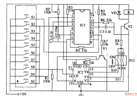
The electronic password switch circuit is composed of the password input circuit, monostable flip-flop, bistable flip-flop, reset circuit, control executive circuit and count divider, and it is shown in Figure 3-96. Password input circuit is composed of buttons S0-S9. Monostable integrated circuit is composed of the internal time-base circuit of the dual time-base IC IC1 and external components of pin2-6. The bistable flip-flop is composed of IC1's another time-base IC and external components of pin8-13. Count divider circuit is composed of the counter / divider integrated circuit IC2 and resistor Rl and so on. Reset circuit consists of resistors R2, R7, and transistor Vl. Control implementation circuit is composed of setting switches S10-S12 and resistor R8, transistor VZ, relay (or electronic lock) K, diode VD.
(View)
View full Circuit Diagram | Comments | Reading(2344)
Electronic password switch 2
Published:2011/8/8 22:11:00 Author:Ecco | Keyword: Electronic password switch
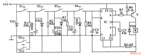
The electronic password switch circuit is composed of the password control circuit and control implementation circuit, and it is shown in Figure 3-97. Password control circuit consists of password control buttons Sl-Sl2, diodes VDl-VD4, resistors Rl-R5, capacitors C1-C5 and four NAND gate IC lC . Control implementation circuit consists of the relay K, diode VD5, transistor V, and resistors R6, R7. Rl-R7 use the 1/4W carbon film resistors or metal film resistors. Cl-C5 select the aluminum electrolytic capacitors with voltage in 16V . VDl-VD4 use 1N4148 silicon switch diodes; VD5 uses the 1N4 1907 silicon rectifier diode.
(View)
View full Circuit Diagram | Comments | Reading(1276)
Two-tone electronic doorbell 1
Published:2011/8/11 1:51:00 Author:Ecco | Keyword: Two-tone electronic doorbell
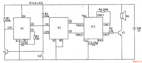
The two-tone electronic doorbell circuit is composed of the input trigger circuit and audio output circuit, ans it is shown in Figure 3-107. The input trigger circuit is composed of the doorbell button S, transistor V1, resistors Rl-R3, capacitor Cl and dual D flip-flop integrated circuit ICl (Al, A2). Audio output circuit consists of the audio output circuit integrated circuit IC2, capacitor C2, resistors R4, R5, transistor V2 and speaker BL. Rl-R5 select the l/8W or 1/4W carbon film resistors. Cl and C2 select the aluminum electrolytic capacitors with voltage in lOV. Vl uses the S9014 or 3DGl2 silicon NPN transistor; V2 uses Sg013 or S8050 silicon NPN transistor.
(View)
View full Circuit Diagram | Comments | Reading(2444)
Two-tone electronic doorbell 2
Published:2011/8/9 22:32:00 Author:Ecco | Keyword: Two-tone electronic doorbell
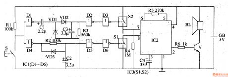
The two-tone electronic doorbell circuit is composed of the trigger control circuit and doorbell generating circuit, and it is shown in Figure 3-108. Trigger control circuit consists of doorbell button S, resistors Rl-R3, electrical wear devices Cl-C3, diodes VDl-VD3, six NOT gate integrated circuit ICl (Dl-D6) and the electronic switch IC lC3 (S1, S2). Doorbell generating circuit consists of the resistors R4-R6, audio IC lC2, capacitor C4, transistor V, and speaker BL. Rl-R6 select the 1/4W metal film resistors or carbon film resistors. Cl-C4 select the aluminum electrolytic capacitors with voltage value being greater than 6V. VDl-VD3 use the 1N4148 silicon switch diodes.
(View)
View full Circuit Diagram | Comments | Reading(2305)
Three-tone electronic doorbell 1
Published:2011/8/15 21:19:00 Author:Ecco | Keyword: Three-tone electronic doorbell
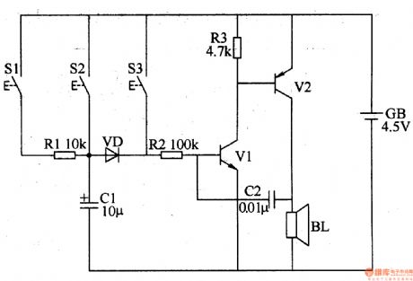
The three-tone electronic doorbell circuit consists of buttons Sl-S3, transistors Vl, V2, speaker BL, resistors Rl-R3, capacitors Cl, C2, diode VD and battery GB, and it is shown in Figure 3-109. Rl-R3 use the 1/4W carbon film resistors or metal film resistors. Cl uses the electrolytic capacitor with voltage in 16V; C2 uses the monolithic capacitors or polyester capacitors. VD uses the 2AP9 germanium ordinary diode or 1N4148 silicon switching diode. Vl uses the 3DG6 or S9013 silicon NPN transistor; V2 uses the 3AX31 germanium PNP transistor.
(View)
View full Circuit Diagram | Comments | Reading(3743)
Three-tone electronic doorbell 2
Published:2011/8/15 21:22:00 Author:Ecco | Keyword: Three-tone electronic doorbell
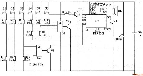
The three-tone electronic doorbell circuit consists of the coding triggered circuit, multi-tone generator and audio amplifier circuit, and it is shown in Figure 3-110. Coding trigger circuit is composed of the buttons Sl-S6, two four-input AND gate (DI, D2) integrated circuit ICI, resistors Rl-Rll and transistors Vl-V3 and so on. Multi-tone sound generator circuit consists of the train sound analog integrated circuit IC2, LEDs VLl and VL2 and resistors R13-Rl5. Audio amplifier circuit consists of audio amplifier tube V4 and speaker BL. Rl-Rl5 use the 1/4W or 1/8W carbon film resistors.
(View)
View full Circuit Diagram | Comments | Reading(4017)
Optical electronic doorbell 1
Published:2011/8/11 20:59:00 Author:Ecco | Keyword: Optical electronic doorbell

The optical electronic doorbell circuit is composed of the power supply circuit and light and sound circuit, and it is shown in Figure 3-111. Power supply circuit consists of the doorbell button S, power transformer T, bridge rectifier UR and filter capacitor Cl. Sound and light circuit consists of colored bulb HL, thyristor VT, music integrated circuit IC, resistors Rl-R3, capacitor C2, diode VD, thyristor VT, LED VL and speaker BL. Rl-R3 use 1/4W metal film resistors or carbon film resistors. C2 and C2 select the aluminum electrolytic capacitors with voltage in lOV. VD uses the 1N4148 silicon switch diode.
(View)
View full Circuit Diagram | Comments | Reading(1867)
Drilling security controller circuit diagram
Published:2011/8/21 21:50:00 Author:Ecco | Keyword: Drilling security controller

The drilling security controller is composed of the trigger switches S1 ~ Sn, resistors R1 and R2, potentiometer RP, capacitors C1 ~ C3, LEDs VL1 and VL2, diodes VD1 and VD2, time-base integrated circuit IC and the relay K, amd it is shown as the chart. R1 and R2 select the 1/4W metal film resistors. RP uses the organic solid carbon resistor or potentiometer. C1 and C3 select the electrolytic capacitors with voltage in 16V; C2 uses the monolithic capacitor or polyester capacitor. VD1 and VD2 use the 1N4007 silicon rectifier diodes. VL1 and VL2 select the φ5mm LEDs, VL1 chooses green, and VL2 chooses red.
(View)
View full Circuit Diagram | Comments | Reading(613)
Three-phase AC phase sequence detector circuit diagram
Published:2011/8/21 21:45:00 Author:Ecco | Keyword: Three-phase AC, phase sequence detector

The three-phase alternating current phase detector circuit is composed of the phase sequence detection circuit, trigger control circuit and LED display circuit, and it is shown as the chart. Phase sequence detection circuit is composed of the rectifier diodes VD1 ~ VD3, resistors R1 ~ R6 and Zeners VS1 ~ VS3. Trigger control circuit consists of four NAND gate integrated circuit IC internal NAND gates D1 ~ D4. LED display circuit consists of NAND gate D4, LEDs VL1, VL2, transistor V and resistors R7, R8. R1 ~ R3 select the 1W metal film resistors: R4 ~ R8 select the 1/4W metal film resistors or carbon film resistors.
(View)
View full Circuit Diagram | Comments | Reading(20614)
Industrial X-ray diagnostic machine delay control switch circuit diagram
Published:2011/8/22 2:51:00 Author:Ecco | Keyword: Industrial, X-ray diagnostic machine, delay control switch

The industrial X-ray diagnostic machine delay control switch circuit is composed of the regulator filter circuit, delay control circuit A, delay control circuit B and control implementation circuit, and it is shown as the chart. Regulator filter circuit is composed of the capacitors C5, C6 and three-terminal voltage regulator integrated circuit IC3. The delay control circuit A is composed of the resistors R1 ~ R3, capacitors C1, C2, time-base integrated circuit IC1, diode VD1, relay K1, LED VL1, control button Sla. Control implementation circuit is composed of the normally closed contacts of the relay K3 and K1, the normally open contacts of K2, high button S2. (View)
View full Circuit Diagram | Comments | Reading(1944)
Industrial electronic ignition circuit diagram
Published:2011/8/22 2:27:00 Author:Ecco | Keyword: Industrial electronic ignition
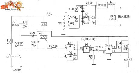
The industrial electronic ignition circuit is composed of the power supply circuit, ignition starter control circuit and boost ignition circuit, and it is shown as the chart. Power supply circuit is composed of the power switch S1, fuse FU, buck capacitor C1, discharge resistor R1, rectifier diode CVD1, voltage regulator diode VS and filter capacitor C2. Start ignition control circuit is composed of the ignition button S2, resistors R5 ~ R7, intergranular tube VT, relay KA and capacitors L4, C5. Boost ignition circuit consists of step-up transformer T, rectifier diodes VD2 ~ VD5, capacitor C3, resistors R2 ~ R4, discharge tube, inductor L and spark plug.
(View)
View full Circuit Diagram | Comments | Reading(2399)
Up / down machine motor overruning brake controller circuit diagram
Published:2011/8/22 2:57:00 Author:Ecco | Keyword: Up / down machine motor , overruning brake controller

The up / down machine motor overruning brake controller circuit is composed of the power supply circuit, LED indication circuit and speed control circuit, and it is shown as the chart. Power supply circuit is composed of the power transformer T, rectifier diodes VD1 ~ VD4, filter capacitors C1, L2, and three-terminal voltage regulator integrated circuit IC2. LED indicator circuit is composed of the light-emitting diodes VL1, VL2, and resistors R4, R5. Speed control circuit is composed of the resistors R1 ~ R6, potentiometers RP1, RP2, operational amplifier integrated circuit IC1 (M, N2), diodes VD5 ~ VD7, transistor V, and relay K.
(View)
View full Circuit Diagram | Comments | Reading(1105)
Motor electronic speed controller circuit diagram 7
Published:2011/8/21 21:42:00 Author:Ecco | Keyword: Motor , electronic speed controller

The electronic motor speed controller circuit consists of wireless remote control transmitter circuit, wireless remote control receiver control circuit, and it is shown as the chart. Wireless remote control transmitter circuit is composed of the micro-power wireless remote control transmitter IC module IC1, time-base integrated circuit IC2, diodes vD1, VD2, resistors R1 ~ R3, potentiometer wireless remote control receiver control circuit is composed of the micro-power wireless remote control receiver IC module IC3, voltage regulator diodes VS1, VS2, resistors M ~ R7, diode VD3, transistor V, solid state relays KN (SSR) and thyristor VT.
(View)
View full Circuit Diagram | Comments | Reading(3957)
HM9902 touching two-state dimmer circuit
Published:2011/8/22 2:37:00 Author:Ecco | Keyword: touching two-state dimmer
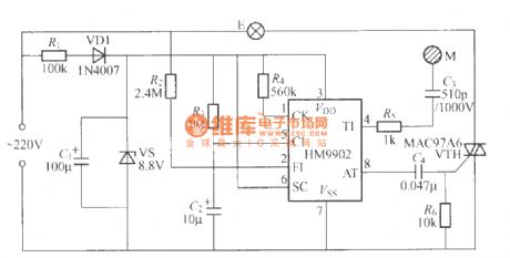
The touching lamp switch circuit made by HM9902 integrated circuit is shown as the chart, and touching M repeatedly, the light bulb E will be lit in the cycle of: light → off → light → off in order to achieve touching on / off action.
(View)
View full Circuit Diagram | Comments | Reading(1873)
The typical application circuit of 5G169 audio lantern control IC
Published:2011/8/8 20:28:00 Author:Ecco | Keyword: typical application circuit, audio lantern , control IC
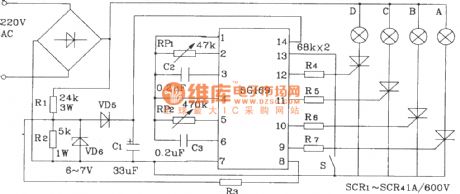
5G169 is the four ways of lights control IC with brightness being slowing. Switch S is the lantern light string loop mode (positive / anti) selector switch, and it is in positive forward cycle when open it and reverse cycle when close it, and RP1, RP2 are used to change the external RC value of Psi ~ vs3 and SA1 ~ SA3. As 5G169 has no audio signal gN-step control, it generally applies to density decorative lights, advertising lights, disco lights, etc., and sound and light can not be synchronized. For synchronization, the audio signal is rectified, coupled and enlarged and then sent to pin 1, pin 2 or pin 4, pin 5 of 5G169. HFC55 is an 8-way lights control IC.
(View)
View full Circuit Diagram | Comments | Reading(745)
| Pages:532/2234 At 20521522523524525526527528529530531532533534535536537538539540Under 20 |
Circuit Categories
power supply circuit
Amplifier Circuit
Basic Circuit
LED and Light Circuit
Sensor Circuit
Signal Processing
Electrical Equipment Circuit
Control Circuit
Remote Control Circuit
A/D-D/A Converter Circuit
Audio Circuit
Measuring and Test Circuit
Communication Circuit
Computer-Related Circuit
555 Circuit
Automotive Circuit
Repairing Circuit