
Circuit Diagram
Index 533
Infrared reflectance electronic doorbell
Published:2011/8/9 21:38:00 Author:Ecco | Keyword: Infrared reflectance, electronic doorbell
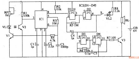
The infrared reflectance electronic doorbell consists of infrared transmitter circuit, infrared receiver circuit, low-frequency oscillator, audio oscillator and audio output circuit, and it is shown in Figure 3-121. Infrared transmitter circuit consists of the infrared transmitter tube (infrared light-emitting diode) VLl, driver transistor Vl, the pin 6 internal cirucuit of integrated circuit ICl and the external components. Infrared receiver circuit consists of infrared / receiver tube (infrared phototransistor) V2 and pin 3 internal circuit of IC1. Low-frequency oscillator consists of the NOR gates Dl and D2 of four NOR gate digital IC ICZ (CD4001) and the resistor R5, capacitor C4 and so on.
(View)
View full Circuit Diagram | Comments | Reading(1956)
Visitors identifying electronic doorbell
Published:2011/8/11 20:13:00 Author:Ecco | Keyword: Visitors identifying, electronic doorbell
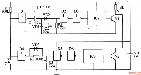
The electronic doorbell circuit is composed of the short pulse identification circuit, long pulse identification circuit and circuit music generating circuit, amd it is shown in Figure 3-120. Short pulse identification circuit consists of the NOT gates D1-D3 which are inside of the six NOT gate integrated circuit ICl, resistors C1, C2 and diodes VD2, VDl. Long pulse identification circuit consists of the NOT gates D4-D6 which are inside of the ICl, resistor R3, diode VD3 and capacitor C3. Music generating circuit consists of the music integrated circuits IC2, 1C3, audio amplification tube Vl and V2, speaker BL and so on. S is the doorbell button. R1 is the current limiting resistor.
(View)
View full Circuit Diagram | Comments | Reading(1200)
Percussion electronic doorbell 2
Published:2011/8/11 21:33:00 Author:Ecco | Keyword: Percussion electronic doorbell
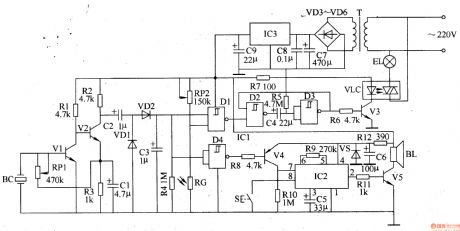
The percussion electronic doorbell circuit is composed of the percussion detection circuit, voltage doubling rectifying circuit, lamp trigger delay control circuit, light control circuit, doorbell trigger circuit, audio circuit and power supply circuit, and it is shown in Figure 3-114. Percussion detection circuit consists of piezoelectric ceramic BC, amplification tubes Vl and V2 and external RC components. Voltage doubling rectifying circuit is composed of the rectifier diodes VDl and VD2, capacitor C3 and other components. Lamp trigger delay control circuit consists of the internal triggers D1-D3 of four NAND gate Schmitt trigger circuit ICl, transistor V3, light coupler VLC and peripheral RC components.
(View)
View full Circuit Diagram | Comments | Reading(1295)
Percussion electronic doorbell 1
Published:2011/8/11 21:21:00 Author:Ecco | Keyword: Percussion electronic doorbell

The electronic doorbell circuit is composed of the pickup amplifier, monostable trigger circuit, pulse counter circuit, music generating circuit and audio amplifier circuit and other components, and it is shown in Figure 3-113. Pickup amplifier circuit consists of piezoelectric ceramic BC, amplification tube Vl, resistors Rl and R2 and capacitor Cl and so on. Monostable trigger circuit is composed of the D flip-flop which is inside of the dual D flip-flop IC and the external components. Pulse counter circuit is composed of decimal pulse counter integrated circuit IC2. Music generating circuit is composed of the music IC IC3 and the external RC components.
(View)
View full Circuit Diagram | Comments | Reading(2375)
Boiler electronic descaling device circuit diagram 4
Published:2011/8/21 21:55:00 Author:Ecco | Keyword: Boiler , electronic descaling device
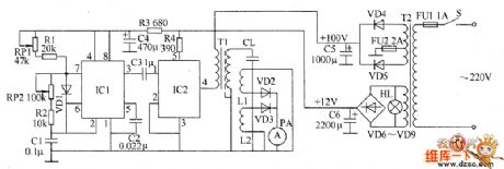
The boiler electronic descaling device circuit is composed of the power supply circuit, 200kHz square wave oscillator, driver amplifier and the output indication circuit, and it is shown as the chart. Power supply circuit is composed of the power transformer T2, rectifier diodes VD4 ~ VD9, filter capacitors C5, C6 and so on. 200kHz square wave oscillator circuit is composed of the time-base integrated circuit IC1 and the external components. Driver amplifier circuit is composed of the high-power electronic switching amplifier IC IC2, output transformer T1 and the capacitive load CL and so on. Output indication circuit is composed of the current meter PA, rectifier diodes VD2, VD3 and current mutual inductance coils L1, L2 and so on.
(View)
View full Circuit Diagram | Comments | Reading(4811)
Punch security controller circuit diagram 4
Published:2011/8/21 22:00:00 Author:Ecco | Keyword: Punch security controller

The punch security controller circuit is composed of the DC power supply circuit, infrared detection control circuit and control implementation circuit, and it is shown as the chart. DC power supply circuit consists of step-down capacitor C1, discharge resistor R1, rectifier diode VD1, voltage regulator diode VS and filter capacitor C2. Infrared detection control circuit is composed of the infrared light emitting diodes VL1 and VL2, infrared phototransistors V1 and V2, resistor R2, potentiometer RP and voltage detection circuit IC. Control implementation circuit is composed of the resistor R3, transistor V3, diode VD2, relay Κand foot switch S.
(View)
View full Circuit Diagram | Comments | Reading(590)
Atmospheric pressure boiler automatic temperature controller circuit diagram
Published:2011/8/21 22:09:00 Author:Ecco | Keyword: Atmospheric pressure boiler, automatic temperature controller

The atmospheric pressure boiler automatic temperature controller circuit is composed of the power supply circuit, temperature detection control circuit, trigger, work status indication circuit and control implementation circuit, and it is shown as the chart. Temperature detection control circuit is composed of the temperature sensor RT, resistors R1 ~ R5, potentiometers RP1, RP2, and operational amplifier integrated circuit IC1 (N1, N2). Trigger consists of four NAND gate IC IC2 internal NAND gates D1 ~ D4. Control implementation circuit is composed of the resistor R7, transistor V, diode VD and relay K. Working status indication circuit consists of current limiting resistor R6 and light-emitting diode VL.
(View)
View full Circuit Diagram | Comments | Reading(2237)
Industrial fuel oil furnace controller circuit diagram 2
Published:2011/8/21 21:38:00 Author:Ecco | Keyword: Industrial , fuel oil furnace , controller

The industrial fuel oil furnace controller circuit is composed of the power supply circuit, testing and ignition control circuit and control implementation circuit, and it is shown as the chart. The power supply circuit is composed of the step-down capacitor C6, discharge resistor R5, voltage regulator diode VS1, rectifier diode VD and filter capacitors C1, C2. Testing and ignition control circuit consists of resistors R1 ~ M, photoresistor RC, capacitors C3 ~ C5, reset button S, voltage regulator diode VS2 and control IC. R2, S, and C4 form the reset circuit; R1, C3 and the RC form the photoelectric detection circuit; R4 and VS2 form the zero-crossing detection circuit.
(View)
View full Circuit Diagram | Comments | Reading(2849)
Three-phase permanent magnet brushless DC motor MC33035 control system circuit diagram
Published:2011/8/22 3:01:00 Author:Ecco | Keyword: Three-phase, permanent magnet , brushless DC motor , control system

View full Circuit Diagram | Comments | Reading(11748)
Permanent magnet brushless DC motor control circuit diagram
Published:2011/8/22 2:43:00 Author:Ecco | Keyword: Permanent magnet , brushless DC motor , control circuit


View full Circuit Diagram | Comments | Reading(1646)
The position detection circuit diagram for rotary transformer
Published:2011/8/21 22:26:00 Author:Ecco | Keyword: position detection , rotary transformer

As the rotary transformer output contains the location information of the analog signal, it is required to process and turn into the digital corresponding location information, then it can control the chip interface with DSP. This requires a corresponding signal conversion circuit which is designed to use a dedicated rotary transformer(digital converter). The system selects the 19XSZ2413-S32-09-A rotary converter, and it is shown as the chart.
(View)
View full Circuit Diagram | Comments | Reading(910)
TEA1046 Dual audio / voice transmission IC diagram
Published:2011/8/22 3:00:00 Author:Ecco | Keyword: Dual audio / voice transmission

TEA1046 dual audio transmission integrated circuit is used in communication equipment for dual tone dialing and voice signal processing. 1. Features TEA1046 integrated circuit contains two-tone dialing signal generator, signal encoding and decoding circuit switching keyboard, voice amplifier, anti-side tone circuit, reference voltage regulator circuit, and other functional circuis. 2. pin function TEA1046 IC uses 24-pin dual in-line package, and the integrated circuit functions are shown in Figure 1-1.
(View)
View full Circuit Diagram | Comments | Reading(998)
TDA1075E microcomputer dialing IC diagram
Published:2011/8/22 2:39:00 Author:Ecco | Keyword: microcomputer dialing IC
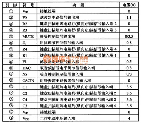
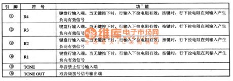
TDA1075E dialing integrated circuit microcomputer system is used in communications equipment for two-tone dialing. TDA1075E integrated circuit includes dual audio dialing generation and key switch codec, mute and other circuits. The IC uses the 18-pin dual in-line package, and the integrated circuit pin functions and data are listed in Table 1-1.
(View)
View full Circuit Diagram | Comments | Reading(869)
CXA1875AM-T4 I (2) C vice bus interface integrated circuit diagram
Published:2011/8/21 22:16:00 Author:Ecco | Keyword: vice bus, interface integrated circuit

CXA1875AM-T4 is the I2C bus interface integrated circuit produced by Japanese Sony, and it is widely used in large-screen flat-panel or big screen picture in picture and other picture-large-screen color TV. 1. FeaturesCXA1875AM-T4 IC contains the binary data signal processing circuit, address bus circuit, IC Bus and other circuit. 2. pin functions and data CXA1875AM-T4 IC uses the DIP 16-pin package, and the integrated circuit pin functions and data are listed in Table 1.
(View)
View full Circuit Diagram | Comments | Reading(601)
Audio / video conversion integrated circuit diagram
Published:2011/8/21 22:21:00 Author:Ecco | Keyword: Audio / video conversion

CXA2069Q is the new model audio / video conversion integrated circuit manufactured by Sony Corporation of Japan, and it is used in the Sony series of picture in picture, back projection color TV. 1. FeaturesCXA2069Q IC's input signal is high / medium frequency component output R / L channel TV audio signal, and the main screen of the video signal CVBSl, Vice-screen video signal CVBS2 and so on. CXA2069Q can also be input the four groups of signals to connect to the audio as Na R / L channel signal input end.2. Pin functions and data XA2069Q IC uses the 64-pin package, the integrated circuit pin functions and data are Table 1.
(View)
View full Circuit Diagram | Comments | Reading(704)
TP509 (A) / TP5094 (A) micro-computer dial-up integrated circuit diagram
Published:2011/8/24 21:58:00 Author:Ecco | Keyword: micro-computer, dial-up integrated circuit

TP5092, TP5092A, TP5094, TP5094A are the micro-computer dial-up integrated circuits produced by TEXAS company, and they are used in communication equipment for two-tone dialing. T5092, TP5092A, TP5094, TP5094A integrated circuits contain two-tone hair number generating circuit and key switch encoding and decoding circuit, and they use 16-pin dual in-line package, and the integrated circuit pin functions are listed in Table 1-1.
(View)
View full Circuit Diagram | Comments | Reading(812)
Mazda data interface circuit diagram
Published:2011/8/24 1:59:00 Author:Ecco | Keyword: Mazda data interface
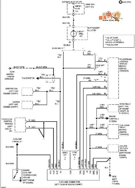
View full Circuit Diagram | Comments | Reading(556)
Mazda external light circuit diagram
Published:2011/8/24 1:58:00 Author:Ecco | Keyword: Mazda external light
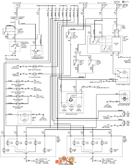
View full Circuit Diagram | Comments | Reading(564)
Mazda bonding distribution circuit diagram
Published:2011/8/24 2:03:00 Author:Ecco | Keyword: Mazda bonding distribution
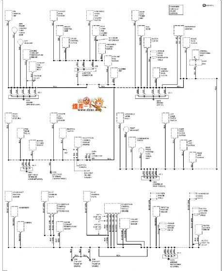
View full Circuit Diagram | Comments | Reading(589)
440bx board structure circuit diagram
Published:2011/8/24 1:57:00 Author:Ecco | Keyword: board structure

View full Circuit Diagram | Comments | Reading(654)
| Pages:533/2234 At 20521522523524525526527528529530531532533534535536537538539540Under 20 |
Circuit Categories
power supply circuit
Amplifier Circuit
Basic Circuit
LED and Light Circuit
Sensor Circuit
Signal Processing
Electrical Equipment Circuit
Control Circuit
Remote Control Circuit
A/D-D/A Converter Circuit
Audio Circuit
Measuring and Test Circuit
Communication Circuit
Computer-Related Circuit
555 Circuit
Automotive Circuit
Repairing Circuit