
Circuit Diagram
Index 520
Three coils voltage relay balance control broken phase protection circuit
Published:2011/8/30 20:47:00 Author:Christina | Keyword: Three coils, voltage relay, balance control, broken phase, protection circuit

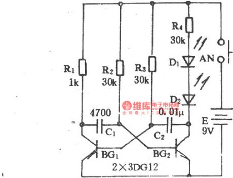
As the figure shows, the electromotor M is operating normally, the three coils of the relay KV are connected with the three-phase AC voltage respectively, the total synthesis suction of the three coils is zero, the contact point will not act. When one of the phases cuts off, the three-phase AC voltage is in the unbalance state to make the voltage relay act, it cuts off the coil power supply of KM, the electromotor M stops operating. The shortcoming of this circuit is that it can not prevent the broken phase of the internal winding of the electromotor M.
(View)
View full Circuit Diagram | Comments | Reading(1892)
Maintenance Circuit of Beijing Cherokee BJ2021 Light Off-road Vehicle AC Generator
Published:2011/8/14 7:37:00 Author:Michel | Keyword: Cherokee, Light Off-road Vehicle, AC Generator, Maintenance Circuit

AC Generator Maintance
Beijing Cherokee uses ko-remy company ac generators, the output current is 56A, maximum output current is 61A.It uses V type more pulley groove.First, rotor.Its structure is similar to domestic ac generator rotor winding resistance and magnetic field is 2.2-3.0 ℃ Ω (When it is 27℃). Second,Stator. Three-phase stator winding is connected in triangular.Third,bridge rectifiers. As a separate parts,it is composed of six diodes.And if one diode is damaged, the rectifier assembly should be replaced.Inspection of the rectifier is shown as figure 1.The multimeter electric block is used to record the resistance value.The two touch needles touch one of the insulation heat sheet 2 and three winding.The other two winding should have the same result according to the above steps, or the diodes are damaged.
(View)
View full Circuit Diagram | Comments | Reading(1006)
Relationship Circuit between Electrolyte Density and Charging Degree of Beijing Cherokee BJ2021
Published:2011/8/14 7:43:00 Author:Michel | Keyword: Electrolyte Density, Charging Degree, Beijing Cherokee, Relationship Circuit

First,storage battery maintenance
The storage battery needs be charged when the discharging degree is over 25%.The relationship between standard density and the charging condition is shown as table.Table:Relationship between Electrolyte Density and Charging Degree
We need to judge whehter the battery can be used by measuring the voltage of current discharging end when it does not start very well.The battery should be fully charged when it is inspected.For 58一475 battery,it needs to keep 240A discharging current and the battery is good and can be used after being charged if the voltage is not less than 9.6V.Otherwise,the battery should be replaced.The domestic 6一QA一60 battery can be used if there is no original battery. (View)
View full Circuit Diagram | Comments | Reading(713)
High Efficiency Charger Circuit of SI8050S
Published:2011/7/23 6:08:00 Author:Michel | Keyword: High Efficiency, Charger Circuit

The above picture is high efficiency charger circuit of SI8050S.There are switch transistor and control circuit within SI8050S.Dividing resistor R1 and R2 are used for setting output voltage and the circuit voltage is 13.72V.Rs is used to test output current and SI8050S output voltage are regulated by VT1 and VT2.Thus it is consistent with voltage of charging batteries and it outputs about 3A constnt current.In this circuit,the input voltage Ui is +17~+30V and the maximum output voltage U。is 13.8V and the current is 3A.Rs resistance value is confirmed according to the following formula,namely,Rs=UBE/3A=0.7V/3A≈0.23Ω and 0.22Ω is chosen in the circuit. (View)
View full Circuit Diagram | Comments | Reading(1998)
The electromotor controlled by five ST-microelectronics
Published:2011/8/30 2:16:00 Author:Christina | Keyword: electromotor, five ST-microelectronics

View full Circuit Diagram | Comments | Reading(685)
Sun Battery Charger Circuit
Published:2011/7/23 6:47:00 Author:Michel | Keyword: Sun Battery, Charger Circuit

The above picture is sun battery charger circuit.Electronic filter (VT5) and regulating diode,VD3 constitute regulating circuit.Its stable voltage is used as benchmark voltage of A2 reverse phase input terminal.Measuring battery voltage of resistance R1,R2,R3 and RP1 are added to A2 phase input terminal. When it is lower than benchmark voltage,A2 outputs low PWL,VT3,VT1 and VT2 conduct.If the sun battery voltage is higher than the backup battery voltage,it begins to charge the backup voltage.A1 test sun battery voltage is lower thsn backup battery voltage,A1 outputs low PWL.G3 and G4 are harmonic oscillators and it produces 15 ms pulse every 15s.A1 compares backup battery voltage and the sun battery voltage,for example,VT1 and VT2 is still in cut-off condition if sun battery is lower than backup battery. (View)
View full Circuit Diagram | Comments | Reading(1759)
Charging Power Failure Alarm Circuit
Published:2011/7/23 7:39:00 Author:Michel

The above picture is charging power failure alarm circuit.When there is AC 220V voltage,VD1, VD2 and R1, R2 generate opposite phase,VT1 stops and H lamp does not spark.When AC is cut,battery voltage is used as power supply,VT1 is added to offset voltage via VD4 and R3.At the moment,VT1 conducts,lamp H sparks,which stands by that AC power is in power failure condition.The AC is turned on,VS2 conducts and power charges the battery.if the charging is finished,C1 is charged and provides gate triggering signal for VS1 and VS1 conducts and VS2 stops at the time.If the circuit is off,VT1 conducts lamp H sends out warning signal. (View)
View full Circuit Diagram | Comments | Reading(1550)
Beijing Cherokee BJ2021 Light Off-road Vehicle Starter Parameter Circuit
Published:2011/8/14 8:22:00 Author:Michel | Keyword: Cherokee, Off-road Vehicle, Starter Parameter Circuit

It uses DW1·4 electromagnetic control type and permanent magnet decelerating starter produced by Germany Bosch company.It uses three permanent magnets to replace the magnetic field winding and the core.It adds one level planetary gear reducer,which greatly reduces the volume and quality of starter.The starter's relative parameter are shown as table 1.
Tabke 1:Starter Parameter (View)
View full Circuit Diagram | Comments | Reading(670)
Parallel Connection Regulating Circuit of TL431
Published:2011/7/24 7:09:00 Author:Michel | Keyword: Parallel Connection, Regulating Circuit

The picture a and b are parallel connection regulating circuits of TL431.The minimum current of regulating circuit (a) is 200μA,maximum current can reach 8A and dynamic range is 91.8dB.The minimum current of regulating circuit (ab) is 1mA,maximum current can reach 8A and dynamic range is 78dB.This circuit can be used as power regulating tube and its main application is as follows.
Fisrt,it is used as parallel connection regulating circuit(high power regulating tube)with large current(8A)and high accuracy.Second,it is used as power supply circuit which changes +5V voltgae into +3.3V/8A.Third,it is used in voltage clamp with large current and high accuracy and thus it can be used as overvoltage protection circuit of DC power supply.TL431 cathode voltage range is main difference of circuit (a)and (b). (View)
View full Circuit Diagram | Comments | Reading(2617)
AN5534 field scanning output integrated circuit
Published:2011/8/24 20:57:00 Author:Christina | Keyword: field scanning, output, integrated circuit


The AN5534 is designed as the field scanning output integrated circuit that is produced by the Panasonic company, and this device can be used in all kinds of domestic and imported color TVs.
1.Features
The AN5534 is composed of the field oscillation sawtooth wave signal generating circuit, the field incentive and output circuit. The internal circuit block diagram and the typical application circuit are as shown in figure 1-18.
2.Pin functions and data
The AN5534 uses the 12-pin single row DIP package, and it can be used in the ChangHong IR2116N series color TV, the pin functions and data are as shown in table 1-18.
(View)
View full Circuit Diagram | Comments | Reading(2487)
AN5151 monolithic TV signal processing integrated circuit
Published:2011/8/24 22:03:00 Author:Christina | Keyword: monolithic, TV signal, processing, integrated circuit


The AN5151 is designed as the monolithic TV signal processing integrated circuit that is produced by the Panasonic company, and it can be used in the 3.5 ~ 5.5 inches small screen TVs.
1.The internal circuit block diagram
The AN5151 has the functions of image and accompanying sound medium amplification, the AGC medium amplification, the AGC high amplification, AFC, AFT, line and field scanning oscillation. The internal circuit block diagram is as shown in figure 1-16.
2.The typical technical data
The typical technology parameters of the AV5151 are as shown in table 1-15.
3.The functions and data of pin-5
The AV5151 uses the dual-row 28-pin DIP package, the pin functions and data are as shown in table 1-16.
Tip: The similar products of AN5151 are KA2951, AV5150. The KA2915 can replace the AN5151 directly, the most of functions and pin functions of AV5150 are the same as the AV5151.
(View)
View full Circuit Diagram | Comments | Reading(1543)
Electric fan infrared remote control circuit (1)
Published:2011/8/24 21:12:00 Author:Christina | Keyword: Electric fan, infrared, remote control
Electric fan infrared remote control circuit (1) (View)
View full Circuit Diagram | Comments | Reading(1388)
Electric fan infrared remote control circuit (2)
Published:2011/8/24 21:14:00 Author:Christina | Keyword: Electric fan, infrared, remote control
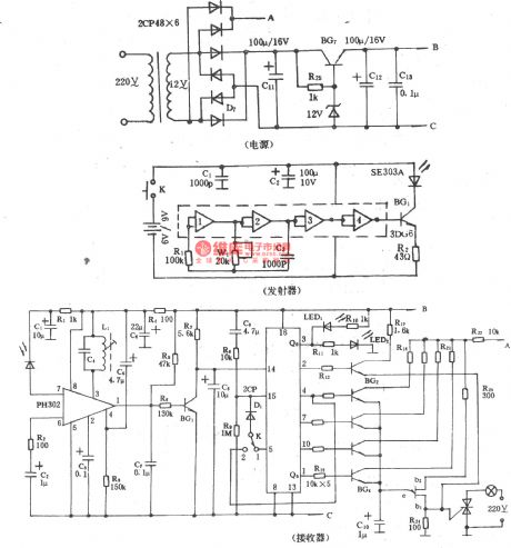
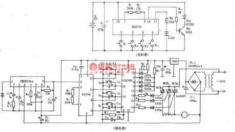
The emitter:
The receiver:
(View)
View full Circuit Diagram | Comments | Reading(1045)
Electric fan infrared remote control circuit (4)
Published:2011/8/24 21:15:00 Author:Christina | Keyword: Electric fan, infrared, remote control
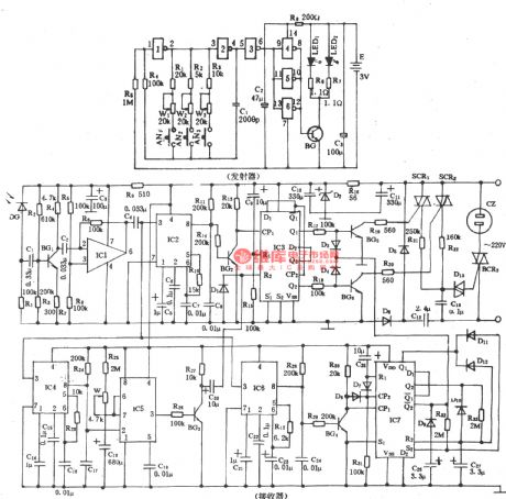
Electric fan infrared remote control circuit (4) (View)
View full Circuit Diagram | Comments | Reading(1492)
Electric fan infrared remote control circuit (3)
Published:2011/8/24 21:15:00 Author:Christina | Keyword: Electric fan, infrared, remote control
Electric fan infrared remote control circuit (3) (View)
View full Circuit Diagram | Comments | Reading(1499)
Electric fan infrared remote control circuit (5)
Published:2011/8/24 21:16:00 Author:Christina | Keyword: Electric fan, infrared, remote control
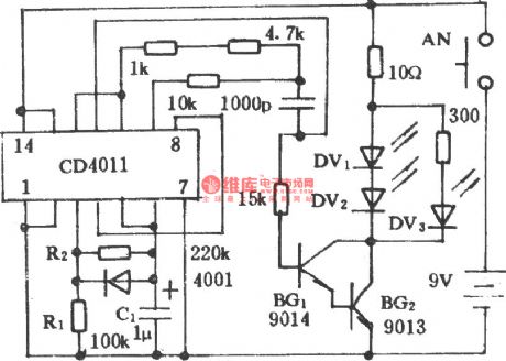

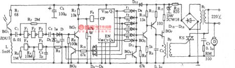
The emitter:
The receiver:
(View)
View full Circuit Diagram | Comments | Reading(1283)
Acousto-optic double-control two-way water color-light music sound circuit
Published:2011/8/30 1:58:00 Author:Christina | Keyword: Acousto-optic, double-control, two-way, water, color-light, music, sound circuit

As the figure shows, it is composed of the voice-activated electronic switch, the light control switch, the monostable trigger, the controlled multi-vibrator, the music sound circuit, the count / cycle pulse distribution circuit, the six channels color light driving circuit and the AC step-down rectifier circuit. It has the two-way running water function, and it has some sweet songs.
(View)
View full Circuit Diagram | Comments | Reading(1647)
Sound and light double control electrical switch socket circuit
Published:2011/8/30 2:00:00 Author:Christina | Keyword: Sound, light, double control, electrical switch, socket circuit

As the figure shows, it is composed of the acoustic/electric transducer sensing switch, the light control switch, the SCR control circuit, the music sound circuit and the AC step-down rectifier circuit.
(View)
View full Circuit Diagram | Comments | Reading(1261)
Sound control electric fan speed governing and the cricket voice control circuit
Published:2011/8/30 2:07:00 Author:Christina | Keyword: Sound control, electric fan, speed governing, cricket voice, control circuit
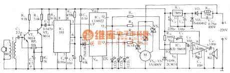
As the figure shows, it is composed of the sound control sensor, the audio-frequency amplifier, the monostable trigger circuit, the pulse count/distribution circuit, the SCR speed control circuit, the cricket sound circuit and the AC step-down rectifier circuit. This circuit uses the triggering sound control mode, and it has the three-stage wind-speed control and stalled control functions, when the fan is blowing, there is the sound of cricket. It has strong anti-interference characteristic.
(View)
View full Circuit Diagram | Comments | Reading(1757)
Fusible Line Circuit of Beijing Cherokee Light Off-road Vehicle
Published:2011/8/14 8:06:00 Author:Michel | Keyword: Cherokee, Light Off-road Vehicle, Fusible Line Circuit

Third, Fusible Line
The fusible line protects the line in a circuit system when it is short-circuit.The color code of the fusible line stands for its specification(It is shown as table 26-7).When the fusible line is broken,we have to find out the fault reason.After the fault is completely excluded and it starts to work as usual,the line can be replaced by the same specification fusible line with polyethylene insulation sleeve.
Table: Fusible Line Circuit of Beijing Cherokee Light Off-road Vehicle (View)
View full Circuit Diagram | Comments | Reading(623)
| Pages:520/2234 At 20501502503504505506507508509510511512513514515516517518519520Under 20 |
Circuit Categories
power supply circuit
Amplifier Circuit
Basic Circuit
LED and Light Circuit
Sensor Circuit
Signal Processing
Electrical Equipment Circuit
Control Circuit
Remote Control Circuit
A/D-D/A Converter Circuit
Audio Circuit
Measuring and Test Circuit
Communication Circuit
Computer-Related Circuit
555 Circuit
Automotive Circuit
Repairing Circuit