
Circuit Diagram
Index 505
High Current Switching Regulator Made Of DN-41
Published:2011/9/6 6:52:00 Author:Felicity | Keyword: High Current, Switching Regulator

View full Circuit Diagram | Comments | Reading(668)
Portable Multi-charging Circuit Made Of LS325A
Published:2011/9/6 6:55:00 Author:Felicity | Keyword: Portable, Multi-charging

View full Circuit Diagram | Comments | Reading(911)
Regulator DC-DC Circuit and Pin of Power Supply Monitor and its Main Features
Published:2011/9/6 22:02:00 Author:Zoey | Keyword: Regulator, DC-DC Circuit, Pin of Power Supply Monitor, Main Features

MAX1691 voltage-Monitor has an 3.0-V, 125-mAh lithium cell, thus the reset time will be postponed for 200ms. Its working current is 35mA, spare current is 1A. This monitor plays an importantrole in protecting RAM and EEPROM and it can work as a watchdog circuit. (View)
View full Circuit Diagram | Comments | Reading(706)
Car emergency flashlight circuit diagram
Published:2011/9/6 4:21:00 Author:Lucas | Keyword: Car emergency flashlight

The dual-transistor amplifier with renewable feedback generates the repetition pulse with period in 60ms, and it provides several ampere of current for low-voltage lamp to make the lamp flash in high brightness, and it will not damage the bulb.
(View)
View full Circuit Diagram | Comments | Reading(1018)
Dance hall strobe light circuit diagram
Published:2011/8/29 2:55:00 Author:Lucas | Keyword: Dance hall, strobe light

B1 in the circuit is step-up coil and hollow coil, and the primary is 12 turns with the diameter in 10mm, and it provides high voltage for strobe bubble. 220V mains voltage is voltage-multiplied and rectified to provide about 630V operating voltage at both ends of the strobe bulb. Adjusting W1 can change the charging rate of C2, thus it changes the trigger diode CB3 conduction frequency (DB3 trigger voltage is about 20V), thenit can control the strobe's frequency.
(View)
View full Circuit Diagram | Comments | Reading(1510)
The clock circuit for driving trigger flashing circuit
Published:2011/8/29 2:44:00 Author:Lucas | Keyword: clock circuit , driving trigger flashing
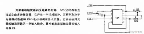
555 timer is connected as free multivibrator, which generates a string of timing pulses, and the frequency depends on the value of the capacitor and the adjusting position of 1MΩ potentiometer. It automatically provides a string of input pulse to the flasher trigger, and the pulse output is connected to the trigger input capacitor C1.
(View)
View full Circuit Diagram | Comments | Reading(483)
White LED Driver with High Efficiency
Published:2011/8/11 8:17:00 Author:Sue | Keyword: White, LED Driver, High Efficiency

View full Circuit Diagram | Comments | Reading(914)
Phone Flasher circuit diagram
Published:2011/9/6 3:55:00 Author:Lucas | Keyword: Phone Flasher

When the phone rings, the BG2 makes IC1A output high, and in one NAND gate end of IC2B, R4, C1 forms the differential circuit to generate spike pulse and trigger IC2B NAND gate, so that the gate outputs low, D3 is conduction , the charge on the capacitor C3 rapidly discharges and remains low, then it is in high level by IC1B inverter, and the oscillator pulse can be sent to the transistor by IC2D and IC2A NAND gates, and the LED flashes with the pulse changes. When the phone is not hung up, the DC voltage on telephone lines is not enough to make the optocoupler output low level.
(View)
View full Circuit Diagram | Comments | Reading(1321)
Heavy Current LED Driver LTC3454
Published:2011/8/12 6:42:00 Author:Sue | Keyword: Heavy Current, LED, Driver

View full Circuit Diagram | Comments | Reading(777)
Photoelectric Automatic Counter
Published:2011/8/12 6:54:00 Author:Sue | Keyword: Photoelectric, Automatic, Counter

The picture shows the working principle of the photoelectric automatic counter. It is made of singlechip PIC16C57. It is suitable in industrial automated production and has some use values. (View)
View full Circuit Diagram | Comments | Reading(896)
LED matrix driver circuit diagram
Published:2011/9/6 4:02:00 Author:Lucas | Keyword: LED matrix driver

In this circuit, the National's MM74C908/MM74C918 dual CMOS driver is connected as the oscillator with Schmitt trigger type; R1, R2 are used to generate hysteresis, and R3, C are the inverted timing components, R4 is the down load of the first driver. The current-driving capability is greater than 250mA, so it can be used to the LED matrix or light bulbs.
(View)
View full Circuit Diagram | Comments | Reading(1263)
LED flasher circuit diagram
Published:2011/9/6 4:07:00 Author:Lucas | Keyword: LED flasher

The two gates of SN7400 four gates form a multivibrator, of which oscillation frequency is very low, so the LED is turned on and off slowly, then you can see the multivibrator working condition from the lamp light turning on and off. The capacity of two capacitors must be the same. This circuit is suitable for teaching demonstration in the classroom, or in science and technology exhibition.
(View)
View full Circuit Diagram | Comments | Reading(895)
Short Circuit Tester
Published:2011/8/11 6:31:00 Author:Sue | Keyword: Short Circuit, Tester

The picture shows the short circuit tester. As seen in the picture, it can test any short circuit on the cable or printed circuit board conveniently,after the components are welded.When the tester approaches the short circuit point, the tone will become higher accordingly. (View)
View full Circuit Diagram | Comments | Reading(836)
Square Wave and Triangular Wave Generating Circuit
Published:2011/8/11 6:00:00 Author:Sue | Keyword: Square Wave, Triangular Wave, Generating

Figure 5-11 Triangular wave, square wave generating circuit (View)
View full Circuit Diagram | Comments | Reading(589)
General Active Filter Circuit
Published:2011/8/19 6:52:00 Author: | Keyword: General, Active Filter

In the circuit, its center frequency f0=3.4kHz, and the trap frequency fe=9.5kHz, the quality factor Q=3.4. For the high frequency filter, the transmittance is 0.1. For the band pass filter, it's 1. For the low frequency filter, it's 1. For the trap frequency filter, it's 10. f0Q≤200kHz. When the output sine wave signal is beyond 10v, its highest frequency is lower than 200kHz. (View)
View full Circuit Diagram | Comments | Reading(616)
Inverting dual flasher circuit diagram
Published:2011/9/6 4:13:00 Author:Lucas | Keyword: Inverting dual flasher

In this circuit, the National's MM74C908/MM74C918 dual CMOS driver is connected as Schmitt trigger type oscillator, and the output of each driver is connected to LED, so the flashing time of the circuit just has the difference in 180 degree. Driver's output current is high enough to drive the array with two light-emitting diodes.
(View)
View full Circuit Diagram | Comments | Reading(907)
Multivibrator Circuit Composed of 74HC123
Published:2011/8/23 7:17:00 Author: | Keyword: Multivibrator

The picture shows the multivibrator circuit which is composed of 74HC123. In the figure 6-18, (a) shows the circuit of 74HC123's Q andits output pulse when the input signal's trailing edge is put on A terminal. (b) shows the circuit of 74HC123's Q andits output pulse when the input signal's rising edge is put on B terminal. The output pulse's width Tw is determined by R1,C1, which means Tw=R1C1. C1's accumulated electric charge is released through pin15 or pin7. When C1's capacitance is large, in order to reduce pin7's or pin 15's discharge current, R1 can be connected to the diode VD1 in parallel. C1's discharge current can get into +UCC directly through VD1 so that it can protect 74HC123. (View)
View full Circuit Diagram | Comments | Reading(6865)
Remote control doorbell circuit diagram
Published:2011/9/5 3:31:00 Author:Lucas | Keyword: Remote control doorbell
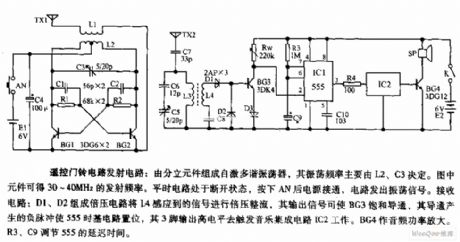
The self-excited multivibrator is composed of the discrete components, and the oscillation frequency is mainly decided by L2, C3. The transmitting frequency is 30 ~ 40MHz gotten by the components shown as the figure. Usually, the circuit is disconnected, pressing the AN will make power on, and the circuit will emit oscillation signal. Receiver circuit: D1, D2 form the doubler circuit, which can double and rectify the signal sensed by L4, and the output signal can make BG3 saturated conduction, then the conduction will generate the negative pulse to set the time base circuit 555, and its pin 3 outputs high level to trigger the music integrated circuit IC2. BG4 is used as audio power amplifier. R3, C9 can adjust the delay time of 555.
(View)
View full Circuit Diagram | Comments | Reading(2145)
LED Electronic Clock with Six Functions
Published:2011/8/11 6:41:00 Author:Sue | Keyword: LED Electronic Clock, Six Functions

The picture shows the LED electronic clock with 6 functions which is composed of XY01 module. Itcandisplay month, day, hour, minute, second and it has a quarter-bell. (View)
View full Circuit Diagram | Comments | Reading(619)
Voice electronic doorbell circuit diagram
Published:2011/9/6 3:44:00 Author:Lucas | Keyword: Voice electronic doorbell

The circuit consists of integrated circuit IC, resistor R, capacitors C1, C2 and button SB, speaker BL, power supply and other components. When people press the doorbell button SB, IC is triggered to work. The memory voice signal is amplified by the transistor to promote the speaker and emit loud voice. C1 is used to eliminate the noise signal sensed by SB long lead.
(View)
View full Circuit Diagram | Comments | Reading(1310)
| Pages:505/2234 At 20501502503504505506507508509510511512513514515516517518519520Under 20 |
Circuit Categories
power supply circuit
Amplifier Circuit
Basic Circuit
LED and Light Circuit
Sensor Circuit
Signal Processing
Electrical Equipment Circuit
Control Circuit
Remote Control Circuit
A/D-D/A Converter Circuit
Audio Circuit
Measuring and Test Circuit
Communication Circuit
Computer-Related Circuit
555 Circuit
Automotive Circuit
Repairing Circuit