
Circuit Diagram
Index 508
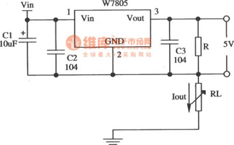
application circuit of constant current source of W7805
Published:2011/8/26 3:28:00 Author:chopper | Keyword: application circuit, constant current source
View full Circuit Diagram | Comments | Reading(938)
expansive flow application circuit of LWY8 positive integrated voltage stabilizer
Published:2011/8/26 3:33:00 Author:chopper | Keyword: application circuit, positive integrated, voltage stabilizer

View full Circuit Diagram | Comments | Reading(625)
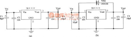
typical application circuit of CW78L××,W78M××,W78H××
Published:2011/8/26 3:30:00 Author:chopper | Keyword: typical, application circuit
View full Circuit Diagram | Comments | Reading(501)
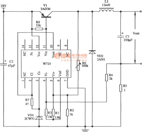
application circuit of switch type constant current source of W723
Published:2011/8/26 3:31:00 Author:chopper | Keyword: application circuit, switch type, constant current source
View full Circuit Diagram | Comments | Reading(585)
simple light-controlled switch
Published:2011/8/28 4:24:00 Author:chopper | Keyword: simple, light-controlled switch

As shown,it is a simple light-controlled switch. In some public places such as corridor, street lightthere are automatical light-controlled switches, which is not only convenient but also saving energy. It will automatically turn on in the dark,and turn offautomatically when it is light.Adjustable 4.7MΩ potentiometeris applicable to different types of photosensitive resistors and can light under certain conditions (dark level). (View)
View full Circuit Diagram | Comments | Reading(1994)
Homemade photoelectric coupler
Published:2011/9/2 23:24:00 Author:chopper | Keyword: Homemade, photoelectric coupler
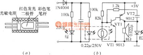
Combine the Φ55mm red LED andphotosensitive resistorby transparent tape and put them into a color pen-holder (black is good),then seal the two ends with glue, and it becomes an photoelectric coupler, which is applied for low-frequency switching circuit,just as shown in Figure (a) . Figure (b) is a outage alarm circuit made by photoelectric coupler, which can send an alarm when the power fails.When the power is available,the red LED of the photoelectric coupler is bright and the resistance of thephotosensitive resistor will decrease after coupling,then VT1 stops,and the oscillator formed by VT1,VT2 does not run. (View)
View full Circuit Diagram | Comments | Reading(1371)
bridge type photoelectric detector formed by photosensitive resistor
Published:2011/9/2 23:22:00 Author:chopper | Keyword: bridge type, photoelectric detector, photosensitive resistor

In the industrial photoelectric measuring device, the photosensitive resistor can form the bridge type photoelectric detector, which is shown in the picture. Two same model (darkness resistance equivalent)photosensitive resistors are used as the bridge arms, one for photoelectric detection, and the other sealed with black tape to avoid light for temperature compensation.This bridge type photoelectric detector can adopt the DC or AC. When using AC modulation, it outputs AC signals to reduced null drift of the amplifier. (View)
View full Circuit Diagram | Comments | Reading(1414)
Light automatic regulator circuit
Published:2011/8/28 4:19:00 Author:chopper | Keyword: Light, automatic regulator
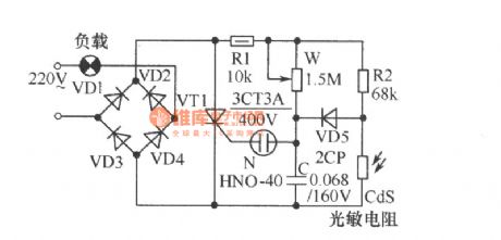
As shown, the circuit can adjust light level according to the strength of outside light automatically. If the external brightness is high, light will be dark, whereas the brightness is low, light will be bright. The thyristor VT1 and diodes VD1~VD4 in figure form full-wave phased circuit with the neontube N as trigger tube of VT1.AdjustingW canchange the charging time constant of capacitor C, that is to change the conduction angle of VT1, in order to control the brightness of the light. (View)
View full Circuit Diagram | Comments | Reading(1515)
Beam blocking alarm
Published:2011/8/25 20:50:00 Author:chopper | Keyword: Beam, blocking alarm
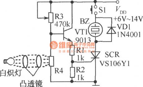
As shown,when the photosensitive resistor R4 is under light, its resistance is small, so the transistor VT1 and unidirectional thyristor SCR are closed; when the beam is blocked, base voltage of VT1rises, and VT1, SCR is conductive, and buzzer BZ will have the power and send an alarm. S1 is the reset switch. When S1 is pressed, the circuit stops the alarm.
(View)
View full Circuit Diagram | Comments | Reading(1255)
precise optical and black control circuit
Published:2011/8/25 20:46:00 Author:chopper | Keyword: precise, optical and black, control circuit

The precise optical and black control circuit is shown as picture. Sinceittakes some positive feedback through R5, changes will be slight behind the actionif the light changes, in order to avoid the frequent jitterof relay when light intensityis on the critical state. (View)
View full Circuit Diagram | Comments | Reading(1360)
photorelay
Published:2011/8/25 20:39:00 Author:chopper | Keyword: photorelay

If you use the photosensitive resistoras the optical switch circuit,its sensitivity is very high.The picture shows the photorelay.When the light is low, VT does not turn on; when there is a certain intensity of light exposure, the resistance ofphotosensitive resistor will get small, and VT will get sufficient base current and get conducted, resulting in a larger collector current, and the relay will close. (View)
View full Circuit Diagram | Comments | Reading(1146)
typical application circuit of LWY8 positive integrated voltage stabilizer
Published:2011/8/26 3:34:00 Author:chopper | Keyword: typical, application circuit, positive integrated, voltage stabilizer

View full Circuit Diagram | Comments | Reading(579)
the principle of gas stove flameout alarm
Published:2011/8/19 7:02:00 Author: | Keyword: principle, gas stove, flameout alarm
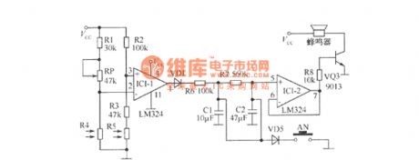
It is very dangerous if the gas stove is out and nobody finds it.Although thetop gas stoveis with automatic flameout control and protection device, the price is too high to spread. The gas stove flameout alarm shown in the picture can monitor the stove and send out the alarm.Core component is LM324 quad op-amp.IC1-1 is a comparator, IC1-2 is a follower; R4, R5 are the photosensitive resistors, the resistance changes with light intensity; AN is a reset switch for discharging the electric charge of capacitors C1, C2. (View)
View full Circuit Diagram | Comments | Reading(1335)
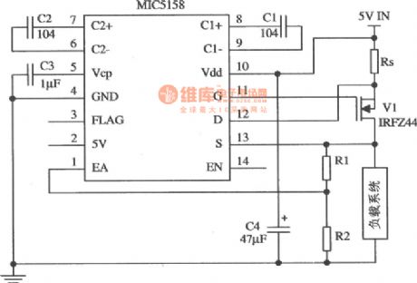
MIC5158 constant current source circuit
Published:2011/8/26 3:35:00 Author:chopper | Keyword: constant current source
View full Circuit Diagram | Comments | Reading(669)
Electronic candles circuit
Published:2011/8/16 2:11:00 Author: | Keyword: Electronic candles

View full Circuit Diagram | Comments | Reading(1358)
photoelectric controlled electrical socket circuit
Published:2011/8/14 1:26:00 Author:chopper | Keyword: photoelectric controlled, electrical socket
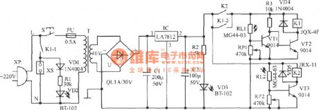
This device adopts ordinary flashlight as remote command,and makes a controlled electrical socket.It can control the power state of electrical socket by pressing the flashlight switch within a few meters,so it is easy to use.IC can be replaced by AN7812,LM7812,W7812 and other models.The current amplification factor β of VT1~VT3 is about 200. RL1 and RL2 use MG44-03 plastic resin encapsulated photosensitive resistors,as well as other ordinary photosensitive resistors whose light photosensitive resistance≤ 5kΩ, dark photosensitive resistance ≥ 1MΩ resistor instead of the . T is the 8W~10W power transformer. (View)
View full Circuit Diagram | Comments | Reading(1316)
application circuit when the TC-3330 monolithic integrated photoelectric switch drives different loads
Published:2011/8/14 1:15:00 Author:chopper | Keyword: application circuit, monolithic, integrated, photoelectric switch, different loads
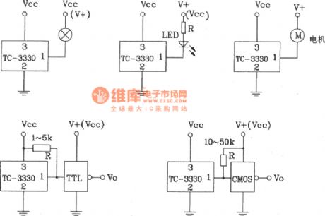
When the TC-3330 monolithic integrated photoelectric switch drives different loads,its application circuit TC-3330 can also be usedon bar code identification,tension sensing, optical cable isolator, paper or object detection, counting, speed measurement and other fields.The photocoupler made by it (diode output type, transistor output type, Darlington type) has excellent performance, high reliability,and wide range of applications. (View)
View full Circuit Diagram | Comments | Reading(1419)
application circuit of light-sensitive control switch of Darlington phototransistor
Published:2011/8/14 1:01:00 Author:chopper | Keyword: application circuit, light-sensitive switch, Darlington, phototransistor
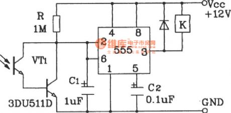
The application circuit of light-sensitive control switch of Darlington phototransistor adopts Darlington phototransistor as the ense organ,so it is sensitive for low-light and it is suitable for the detection of the reflected light signals. (View)
View full Circuit Diagram | Comments | Reading(2165)
application circuit of light triggered switch of Darlington phototransistor
Published:2011/8/14 0:56:00 Author:chopper | Keyword: application circuit, light triggered, switch, Darlington, phototransistor
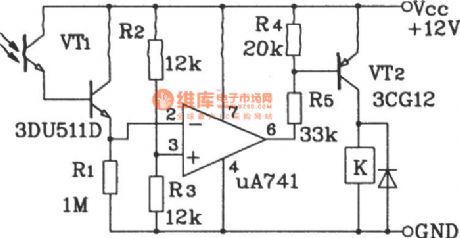
The application circuit of light triggered switch of Darlington phototransistor adopts the sub-type Darlington phototransistor and amplifier, so the weak light can flip the circuit.When the R1 and photodiode are reversed, or the in-phase and reversal phase input ends of the op-amp are reversed,the circuit can be modifiedas the darkness-triggered switch. (View)
View full Circuit Diagram | Comments | Reading(1399)
Inductively coupled CUK power conversion circuit
Published:2011/8/31 2:43:00 Author:John | Keyword: Inductively coupled CUK power conversion

It should be noted that coupled adapter in the figure still uses the symbols of ordinary AC transformer. But in fact there are essential differences between the two: ① DC current can be through the coupled adapter; ②secondary current flow of coupled inductor is on the contrary of that of the AC transformer. As the coupling way only affects the exchange properties, the inductively coupled CUK can maintain the basic characteristics of all transformations, and as well as playing an instant emotional role of energy transfer.
(View)
View full Circuit Diagram | Comments | Reading(1155)
| Pages:508/2234 At 20501502503504505506507508509510511512513514515516517518519520Under 20 |
Circuit Categories
power supply circuit
Amplifier Circuit
Basic Circuit
LED and Light Circuit
Sensor Circuit
Signal Processing
Electrical Equipment Circuit
Control Circuit
Remote Control Circuit
A/D-D/A Converter Circuit
Audio Circuit
Measuring and Test Circuit
Communication Circuit
Computer-Related Circuit
555 Circuit
Automotive Circuit
Repairing Circuit