
Circuit Diagram
Index 504
Regulator DC-DC Circuit and Pin of Power Supply Monitor and its Main Features TA7179P Tracking Regulator
Published:2011/9/6 2:57:00 Author:Zoey | Keyword: Regulator, DC-DC Circuit, Pin of Power Supply Monitor, Main Features, Positive output

TA7179P tracking regulator can output±15V voltage, and this value can be turned to be±8V by using VADJ terminal and external resistance. The current output is 100mA and the temperature drift is 0.007%/℃,the maximum voltage output is ±30V. (View)
View full Circuit Diagram | Comments | Reading(1945)
Regulator DC-DC Circuit and Pin of Power Supply Monitor and its Main Features TA7089P Compressible Regulator(Positive Output)
Published:2011/9/6 3:00:00 Author:Zoey | Keyword: Regulator, DC-DC Circuit, Pin of Power Supply Monitor, Compressible Regulator(Positive Output)

TA8909 adjustable regulator(Positive output) can output adjustable voltage, which ranges from 3.3V to 33V. The maximum current output is 200mA and the typical value of impedance output is 40Ω. The maximum voltage input is 35V, with the power of 600mW. The working temperature is between -30℃ to +75℃. (View)
View full Circuit Diagram | Comments | Reading(1076)
Control and driving circuit diagram of three-phase DC motor in Y connection
Published:2011/9/6 22:52:00 Author:Vicky | Keyword: control and driving circuit, three-phase DC motor, Y connection


In this circuit, the three-phase winding of the motoris in Y connection. If one is conducted by another, when power diode VF1 and VF2 are conducted, the current flows to A phase winding, and then back to the power supply by C phase winging after flowing through VF2. If the torque generated by the current which flows to the windings is positive, then the torque generated by windings is negative. When the motors turnfor60 degrees, VF2 andVF3 are conducted instead of VF1 and VF2. Meanwhile, the current flows to B phase winding from VF3, and then back to the power supply by C phase winding after flowing through VF2. (View)
View full Circuit Diagram | Comments | Reading(1127)
Regulator DC-DC Circuit and Pin of Power Supply Monitor and its Main Features SI-3000C Regulator
Published:2011/9/6 2:58:00 Author:Zoey | Keyword: Regulator, DC-DC Circuit, Pin of Power Supply Monitor, Positive Output

SI-3000C series regulators(positive output ) are five-terminal regulators that have low voltage margins. The voltage output can be 5V, 9V, 12V, 15V and 24V. The outout voltage can also be adjusted by the resistance between remote sensing terminal and output terminal. The output current is 1.5A and the output voltage margin can decrease to less than 0.5V when the current turns to be 1A. Maximum output voltage of SI-3050C and SI-3090C is 35V, SI-3120C and SI-3150C 40V, SI-3240C 45V. The working temperature is between -30℃to +100℃.Each of themhas an interior overcurrent, overvoltage and overtemperature-proof circuit. (View)
View full Circuit Diagram | Comments | Reading(828)
Ozone Box or Xeon lamp weather resistance test chamber
Published:2011/9/7 8:39:00 Author:Vicky | Keyword: Ozone Box, Xeon lamp weather resistance test chamber

Ozone box specification
Type (CM)QL-100 QL-250 QL-500 QL-010
Size of workroom: :45*45*50 50*60*75 70*80*90 100*100*100
Measurement: 115*90*165 120*110*190 135*128*210 165*148*220
Power: 4.0(KW) 4.5(KW) 4.5(KW) 6.5(KW)
Temperature range: 0℃~70℃
Humidity range: ≥65%R.H
Ozone density: 50~1000pphm
Temperature fluctuation range: ±0.5℃
Experiment device: dynamic or static (alternative)
Sample shelf rotate speed: 360°(1 circle/minute)
Gas flow speed: 12~16mm/s
Temperature controller: imported LED displays P、I、D+S、S、R. micro-computer integrated controller Ozone Box
Time controller: high-accuracy hour, minute and second controller Ozone Box
Ozone density analysis: silent discharging tube
Safety protection: leakage of electricity, short circuit, overheat, overheating of motor, over-current protection (View)
View full Circuit Diagram | Comments | Reading(952)
Bi-directional speed-adjusting motor driver circuit diagram
Published:2011/9/7 9:27:00 Author:Vicky | Keyword: bi-directional, speed-adjusting, motor driver circuit

Output and level conversion
Output signal line is introduced by Port. Pin Port1 is the input end of motor direction signal, pin port2 is the PWN signal input end, and pin port3 is the grounding line. Attention that pin port3 is grounded and connected with a 2kΩ resistance. When the driver panel and monolithic provides power respectively, the resistance can provide the backflow passageway for signal circuit. When the driver and monolithic together use a same group of power, the resistance can prevent high current from flowing to the monolithic mainboard ground wire along the line which will lead to interference. Or, it is equivalent to separate the ground wire of the friver panel and the ground wire of monolithic, and to realize “one-point earth fault”. Capacitance C1 prevents the voltage from going down suddenly which is caused by the sudden start-up of the motor. (View)
View full Circuit Diagram | Comments | Reading(1182)
Regulator DC-DC Circuit and Pin of Power Supply Monitor and its Main Features Tracking regulator
Published:2011/9/6 3:25:00 Author:Zoey | Keyword: Regulator, DC-DC Circuit, Pin of Power Supply Monitor, Tracking regulator

Interior output voltage of NJM 2353 tracking regulators is ±15V, and output voltage can be adjusted to 10~23V by the voltage adjusting terminal of the tracking regulator. The output current is ±100mA, maximum output voltage±30V, the power 700mW and the working temperature -20~+75℃. This regulator has an interior current-limiting circuit. (View)
View full Circuit Diagram | Comments | Reading(688)
Regulator DC-DC Circuit and Pin of Power Supply Monitor and its Main Features Swtiched regualtor
Published:2011/9/6 3:39:00 Author:Zoey | Keyword: Regulator, DC-DC Circuit, Pin of Power Supply Monitor, Swtiched regualtor

NJM 2353 switched regulator is a low-power-consumption regulator. It can increase voltage as well as decrease voltage, and the output voltage can be set by the external resistance. The regulator has an interior 1.3-V reference voltage. Maximum voltage of the power supply is 24V. This regulator is dual-inline packaged,with itspowerbeing 500mW, while power of microcapsule is 300mW. Its working temperature is -20~+75℃ (View)
View full Circuit Diagram | Comments | Reading(679)
Diagram of lithium battery protection circuit based on Xysemi XB4251A
Published:2011/9/7 8:09:00 Author:Vicky | Keyword: lithium battery, protection circuit

Schematic of lithium battery protection devices is shown in the above picture, which is realized mainly by battery protection control IC , exterior discharging switch M1 and charging switch M2. When P+/P- end is connected with charger, M1 and M2 are all under conducting state when the battery is charged normally; when the control IC detects any abnormality during charging, M2 is then cut off and charging process stops. When P+/P- end is connected with load, M1 and M2 are all under conducting state when the battery is discharging; when the control IC detects any abnormality, M1 is cut off and discharging process stops.
In addition, XB4301 cannot be reversely connected. XB4301 is mainly used in MP3 and Bluetooth at present, including partial mobiles, GPS application. (View)
View full Circuit Diagram | Comments | Reading(2115)
Regulator DC-DC Circuit and Pin of Power Supply Monitor and Voltage Detector
Published:2011/9/7 3:12:00 Author:Zoey | Keyword: Regulator, DC-DC Circuit, Pin, Voltage-detector

MAX811/MAX812 voltage-detector can detect 3.0-V, 3.3-V and 5.0-V voltage of power supply. Its current of power supply is 6A. Reset pulse width of SE is larger than 140ms. Output of MAX811 and MAX812 is RESET. The detectors have manually-reset function. If voltage of the power supply is less than 1V, MAX811 will keep RESET signal available. (View)
View full Circuit Diagram | Comments | Reading(719)
Regulator DC-DC Circuit and Pin of Power Supply Monitor and Step-up Regulator
Published:2011/9/7 3:33:00 Author:Zoey | Keyword: Regulator, DC-DC Circuit, Pin, Step-up Regulator

MAX732/733 refers to the DC-DC current PWM step-up regulator. As to MAX732, output voltage is +12V, maximum output current is 200mA, output voltage range is +4.0~+9.3V. And as to MAX733, the relevant values are +15V, 125mA and 4.0V~11.V respectively. Typical value of full load efficiency is 85%~92%, of empty load current is 1.7mA. Oscillation frequency is 170 kHz. The regulator has protection circuits for periodic current-proof, overcurrent-proof, undervoltage-proof and programmable soft-start. (View)
View full Circuit Diagram | Comments | Reading(1106)
Regulator DC-DC Circuit and Pin of Power Supply Monitor and Power Supply System
Published:2011/9/7 3:36:00 Author:Zoey | Keyword: Regulator, DC-DC Circuit, Pin, Power Supply System

MAX714/715/716 refers to the power supply system powered by cell piles. It has a micro-processor for detection. This system consists of a four-loop logic-controlled +5-V regulator and a three-loop switched regulator, a fixed positive output single-loop(+12V or +15V), a software-controlled negative output single-loop and a fixed negative single-loop. Its static current is 20A. This system has a spare cell piles switch, a low voltage warner and it can restart if the cell lapses. (View)
View full Circuit Diagram | Comments | Reading(706)
Regulator DC-DC Circuit and Pin of Power Supply Monitor and Linear Debugger
Published:2011/9/7 22:53:00 Author:Zoey | Keyword: Regulator, DC-DC Circuit, Linear Debugger

Working voltage range of MAX687/688/689 is 2.7V~11.0V. Its working current is below 250mA and power-off current is below 1µA. Output voltage of MAX676 and MAX688 is 3.3V, MAX689 is 3.0V. Current for driving external transistor should be larger than 10mA. Voltage will descend to 200mVwhen output currentreaches 500mA(2TX749). The accuracy is ±2%.
(View)
View full Circuit Diagram | Comments | Reading(743)
Double Voltage Boost Circuit Constituted By In Gate Circuit(CD4069)
Published:2011/9/6 5:19:00 Author:Felicity | Keyword: Double Voltage, Boost Circuit, In Gate Circuit

View full Circuit Diagram | Comments | Reading(725)
Electronic Double Voltage Boost Circuit
Published:2011/9/6 5:15:00 Author:Felicity | Keyword: Electronic, Double Voltage, Boost Circuit
View full Circuit Diagram | Comments | Reading(677)
Constant Current Circuit Constituted By MIC29152 With The Output Current Of 1.0A
Published:2011/9/6 5:13:00 Author:Felicity | Keyword: Constant Current Circuit, Output Current, 1.0A

View full Circuit Diagram | Comments | Reading(1435)
Circuit Of Wide-input Voltage Regulator Constituted By MIC29150-12
Published:2011/9/6 5:07:00 Author:Felicity | Keyword: Wide-input, Voltage Regulater

View full Circuit Diagram | Comments | Reading(922)
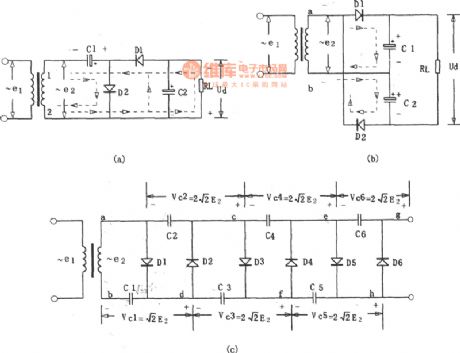
Doubler Rectifier Circuit
Published:2011/9/6 5:21:00 Author:Felicity | Keyword: Doubler, Rectifier
View full Circuit Diagram | Comments | Reading(528)
Switch Power Made With Three-terminal PWM Switching Power Supply IC
Published:2011/9/6 6:44:00 Author:Felicity | Keyword: Switch Power, Three-terminal PWM, Switching Power Supply IC

View full Circuit Diagram | Comments | Reading(4737)
Low-power Miniature Switching Power Supply Made With WS157 Or WS106
Published:2011/9/6 6:48:00 Author:Felicity | Keyword: Low-power, Miniature, Switching Power Supply

View full Circuit Diagram | Comments | Reading(1095)
| Pages:504/2234 At 20501502503504505506507508509510511512513514515516517518519520Under 20 |
Circuit Categories
power supply circuit
Amplifier Circuit
Basic Circuit
LED and Light Circuit
Sensor Circuit
Signal Processing
Electrical Equipment Circuit
Control Circuit
Remote Control Circuit
A/D-D/A Converter Circuit
Audio Circuit
Measuring and Test Circuit
Communication Circuit
Computer-Related Circuit
555 Circuit
Automotive Circuit
Repairing Circuit