
Circuit Diagram
Index 507
Boiler coal conveyor circuit
Published:2011/9/6 1:06:00 Author:TaoXi | Keyword: Boiler, coal conveyor circuit

View full Circuit Diagram | Comments | Reading(1274)
Insufficient light automatic turn-on bird sound circuit
Published:2011/9/6 1:11:00 Author:TaoXi | Keyword: Insufficient light, automatic turn-on, bird sound circuit

As the figure shows, it is composed of the photoelectric sensor integrated circuit ULN3300, the relay control lighting circuit and the bird sound circuit, the AC step-down rectifier circuit.
(View)
View full Circuit Diagram | Comments | Reading(1138)
Insufficient light cock sound alarm circuit
Published:2011/9/6 1:14:00 Author:TaoXi | Keyword: Insufficient light, cock sound, alarm circuit

As the figure shows, it is composed of the ULN3330 photoelectric sensor, the cock sound alarm circuit and the audio amplifier.
(View)
View full Circuit Diagram | Comments | Reading(1032)
Beijing Cherokee car technical specification circuit diagram
Published:2011/8/27 1:37:00 Author:Nancy | Keyword: Cherokee, car technical specification
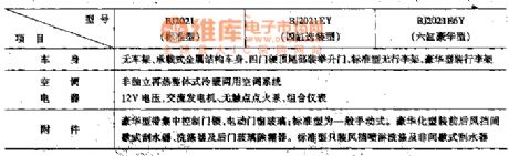
The crankshaft position sensor, synchronous signal sensors, blend air manifold absolute pressure sensor (MAP), cooling fluid temperature sensor, and fire temperature degrees sensors, throttle position sensor, the wheel speed sensors, oxygen sensors, storage battery voltage signal, the ignition switch, air conditioning switch, power steering, braking switch analog, pulse signal and switch signals are all necessary input signals of the computer. (View)
View full Circuit Diagram | Comments | Reading(493)
Basic timing circuit diagram formed by NE555
Published:2011/8/27 1:33:00 Author:Nancy | Keyword: Basic timing
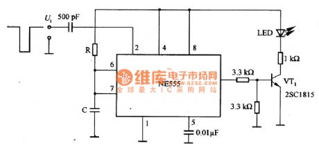
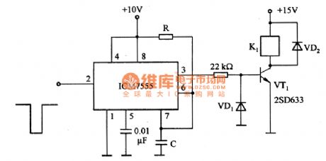
Figure 1 is the basic timing circuit diagram formed by NE555. Figure 1 (a) is the basic timing circuit diagram formed by NE555. In the circuit, if a trigger pulse is added to the pin 2 as shown in the figure 1, then there must be a certain time interval pulse in pin 3 output, the interval is T ~ RC, which is amplified by VT1 to drive the light-emitting diode LED in the related circuit in Figure 1.
Figure 1 (b) is the timing circuit formed by CMOS (ICM7555). It adopts CMOS and has high impedance, the setting time can be greatly extended, for example, it can be used in the timer of a few minutes. In the figure, R is ranging from lkΩ to lOOMΩ, C is ranging from 1OOpF to 10000μF. (View)
View full Circuit Diagram | Comments | Reading(582)
0M1032--Microcomputer dialing integrated circuit diagram
Published:2011/8/27 1:15:00 Author:Nancy | Keyword: Microcomputer, dialing, integrated circuit

0M1032 series microcomputer dialing integrated circuit is widely used in all kinds of communication telephones.
0M1032 integrated circuit contains dialing signal processing circuit, static noise control circuit, key switch encode and decode circuit. The IC adopts 18-pin DIP structure, the pin function and data is shown as the table.
(View)
View full Circuit Diagram | Comments | Reading(512)
Circuit diagram of driving 60 pieces of 20mA constant current LED
Published:2011/9/6 22:47:00 Author:Vicky | Keyword: 20mA constant current LED

Picture 1 shows the 6 channels of LT3598, and the channels are used to drive the 60 pieces of LED. The current of each channel of LED is set at 20mA. Pin CTRL and pin PWM take responsibility of providing simulating dimming function and digital dimming function respectively. True color PWM dimming offers constant LED color and a dimming proportion of 3000/1. Picture 2 shows ±0.5% typical current-matching accuracy between channels of LED. It generates consistent light distribution, which is very important in application in large-scale backlight.
(View)
View full Circuit Diagram | Comments | Reading(3645)
Gas Annunciator Diagrams
Published:2011/9/6 21:21:00 Author:Vicky | Keyword: Gas Annunciator

DAP2101-GP1 combustible gas annunciator control system adopts plug-in annunciator and explosion-proof DTQB-518 type (three wire system, 4~20mA) combustible gas transmitter. When there is combustible gas in the air, the transmitter shall send out a proportional 4-20mA signal corresponding to the combustible gas concentration to the annunciator. The annunciator displays the percentage concentration of lower explosion limit. When the value of concentration reaches the pre-set annunciating value, the annunciator sends out sound and light alarming and control system to warning the operating personnel to take measures to guarantee safety in production and avoid explosive accident.
(View)
View full Circuit Diagram | Comments | Reading(656)
100KHz –100 MHz Noise Elimination Circuit Diagram
Published:2011/9/6 21:18:00 Author:Vicky | Keyword: noise elimination circuit

Noise elimination circuit can be designed in the 100kHz~l00MHz superhigh circuit. It is mainly composed by squelch amplifier AL, control circuit VTl~VT3, relay KNf, and regulated voltage supply A2. The working principle is shown in the above picture. When there is no signal received, the output noise voltage of superhigh frequency is lower than 100MV; the DC voltage of detection wave is very small after being filtered by diode VD1 and capacitances C1 and C2. The voltage enters the integrated amplifier A1via pin ② in the output end , and leaves via @. The voltage remains very small after amplified and cannot drive the triode VT1 to work. VT2 stops working and VT3 is under conducted. Relay KM then works.
(View)
View full Circuit Diagram | Comments | Reading(1182)
Simplified load current strength indicator circuit diagram
Published:2011/9/6 21:16:00 Author:Vicky | Keyword: load current strength indicator

The light strength in the picture is proportional to the load current. The purpose of designing the circuit is to provide a very compact circuit to take the place of electricity meter of 12 V power line in some astronomical devices. The devices contain small-power heating components of invisible working state. However, when the heater is connected, LED would send out light to indicate clearly that they’re connected and working.
The circuit analysis is very simple. The voltage of the two ends of 22ohms resistance is the same with the voltage of the two ends of RSENSE. The current going through the 22 ohms resistance is the same with the current going through LED. Therefore, as to the parameter given by the picture, the current of LED current equals 0.05/22 of the load current. When the load current changes from 200mA to 6.6A, the light of LED becomes fully lighted from weak (confined by 680 ohms resistance).
(View)
View full Circuit Diagram | Comments | Reading(975)
Circulatory timing flashlight circuit diagram
Published:2011/9/6 21:09:00 Author:Vicky | Keyword: circulatory timing flashlight

In accordance with the picture, the circulatory timing control circuit can be composed of very few components. The circuit is composed of MOS time base circuit 7555, CMOS decimal counter (pulse distributor) 4017 and last-stage VMOS power transistor. Power transistor can control lamp bulb of current up to 2A. The resistance Rave between the lamp bulb and power +UB is used to control the current.
The time base circuit frequency is modulated by potentiometer RP (about 0.5 ~ 10Hz), and the nine-stage circulatory register is controlled by the square wave output signal via clock input end, so as to make every output ends turn to high level in turn. Because the pin11 reset input end is connected with pin 15, the first lamp gives out light when the 10th pulse comes.
(View)
View full Circuit Diagram | Comments | Reading(1216)
High resolution quadruple frequency subdivision circuit diagram
Published:2011/9/6 21:03:00 Author:Vicky | Keyword: high resolution, quadruple frequency , subdivision circuit

The above picture is a circuit of quadruple frequency which can not only avoid the false pulse, but also improve the high resolution. Here, it adopts a memorable D-type trigger and clock generator circuit. As shown in picture 4, every channel has two D-type triggers in serial, so that, during the interval of the clock pulse, the two Q ends (such as the corresponding pin2 and pin7 of 74LS175 in channel B) retain the input state of the former two periods. If the two are the same, it means there is no change in the clock interval; otherwise, the change of direction can be judged by the relationship within, and therefore the output pulse of forward direction or reverse direction is generated. (View)
View full Circuit Diagram | Comments | Reading(863)
Diagram of two filter circuits used for AM broadcast interference
Published:2011/9/6 21:00:00 Author:Vicky | Keyword: filter circuit, AM broadcast interference

AM reflecting filter in the picture (a) can be composed of common disk-type ceramic capacitor, silver capacitor, and Panasonic V series polyester capacitor. Though it is better to use digital capacitance meter or capacitance bridge to match with, an allowance of 5 percent for the component can still meet the satisfaction. If silver capacitance is used, it is better to use 1000pF (0.001ptF) capacitance, and the 0.002ptF capacitance can use two 0.001pF capacitances in serial (C1 and C3)。 The average inductance of the circuit is 3.3μH. It can use either isolated regular magnetic chip inductance or non-isolated annular magnetic chip inductance. (View)
View full Circuit Diagram | Comments | Reading(829)
The edge detection circuit using NAND gate
Published:2011/8/8 0:17:00 Author:Sophia | Keyword: edge detection circuit, NAND gate

This circuit is the rising edge detection circuit using the NAND gate previously described, and circuit edge of the output pulse amplitude as T ≈ RC, IC threshold voltage CMOS, T ≈ 0.7RC.
In this circuit, when the input is L , the terminal voltage charge of capacitor C is voltage yDD and becomes high level H . When the input is H , before the C terminal voltage reaches y (T = RC), the output level is L . The figure is the input and output waveform of the edge detection circuit. 10pμs negative pulse will be got since the input begins to rise. (View)
View full Circuit Diagram | Comments | Reading(2974)
precise optical control circuit
Published:2011/8/25 20:54:00 Author:chopper | Keyword: optical, control circuit

The circuit shown in the picture is a precise optical control circuit, and its work is noteffected by supply voltage and ambient temperature. Resistors R1, R2, R6 andphotosensitive resistor R5 form thetwo bridge of Wheatstone bridge together. (View)
View full Circuit Diagram | Comments | Reading(1549)
LED flashlight circuit
Published:2011/8/25 21:20:00 Author:chopper | Keyword: LED, flashlight circuit
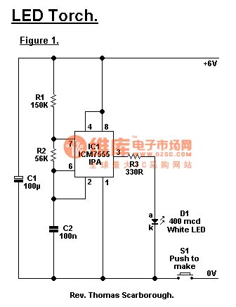
7555 time-based IC(can not use normal 555) is the core of a LED flashlight.A white light-emitting diode (if you can not find one, just take other colors) is issued about 400mcd brightness when it works, so that when it focuses, it can illuminate objects in 30 meters. The approach to focus is to install a short focal length focusing lens in front of LED . If you want to use other voltage values, the value of resistor R3 must be modified: 9V - 470 Ω 12V - 560 Ω (View)
View full Circuit Diagram | Comments | Reading(2360)
CW7805 constant current source circuit
Published:2011/8/26 3:23:00 Author:chopper | Keyword: constant current source

View full Circuit Diagram | Comments | Reading(1158)
CW7805 constant current source circuit with adjustable output current
Published:2011/8/26 3:24:00 Author:chopper | Keyword: constant current source, adjustable, output current

View full Circuit Diagram | Comments | Reading(949)
constant current source application circuit of Wll7,W217,W317
Published:2011/8/26 3:25:00 Author:chopper | Keyword: constant current source, application circuit

View full Circuit Diagram | Comments | Reading(602)
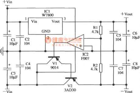
application circuit of regulated power supply in tracking mode of W7800
Published:2011/8/26 3:28:00 Author:chopper | Keyword: application circuit, regulated power supply, tracking mode
View full Circuit Diagram | Comments | Reading(563)
| Pages:507/2234 At 20501502503504505506507508509510511512513514515516517518519520Under 20 |
Circuit Categories
power supply circuit
Amplifier Circuit
Basic Circuit
LED and Light Circuit
Sensor Circuit
Signal Processing
Electrical Equipment Circuit
Control Circuit
Remote Control Circuit
A/D-D/A Converter Circuit
Audio Circuit
Measuring and Test Circuit
Communication Circuit
Computer-Related Circuit
555 Circuit
Automotive Circuit
Repairing Circuit