
Circuit Diagram
Index 515
Division circuit diagram
Published:2011/8/19 1:50:00 Author:Jessie | Keyword: Division

As shown in figure:
A1 forms Voltage controlled current source, A2is thevoltage comparator, A3 is the active low-pass filter. When time constant R1C1 equals to clock pulse cycle T, the relationship between input and output of circuit is: Vo=-V2E/V1. If make E = 1V, there were Vo=-V2/V1. V1 and V2 are required to bepositive, limited in 10V, the V2 is slightly below V1. Resistance R1, R2 and capacitance C1 required tousethe components with goodtemperature stability. A1 is HA2-2520,A2, A3 are LM101A. (View)
View full Circuit Diagram | Comments | Reading(752)
Buick ant-locking braking circuit diagram
Published:2011/8/19 0:48:00 Author:Jessie | Keyword: Buick , ant-locking braking circuit

View full Circuit Diagram | Comments | Reading(588)
Buick reversing light circuit diagram( without light dimming control)
Published:2011/8/19 0:49:00 Author:Jessie | Keyword: Buick , reversing light , light dimming control

View full Circuit Diagram | Comments | Reading(554)
Buick demisting circuit diagram(demisting boneville wc61)
Published:2011/8/19 0:50:00 Author:Jessie | Keyword: Buick, demisting, boneville wc61

View full Circuit Diagram | Comments | Reading(619)
Lm1875T Hi-Fi 30w audio power amplifier circuit diagram 1
Published:2011/8/19 1:10:00 Author:Jessie | Keyword: Hi-Fi , 30w , audio power amplifier

View full Circuit Diagram | Comments | Reading(3065)
Buick air conditioning circuit diagram(automatic air conditioning)
Published:2011/8/19 1:02:00 Author:Jessie | Keyword: air conditioning , automatic, Buick

View full Circuit Diagram | Comments | Reading(1148)
Lm1875T Hi-Fi 30w audio power amplifier circuit diagram 2
Published:2011/8/19 0:58:00 Author:Jessie | Keyword: Hi-Fi , 30w audio, power amplifier

View full Circuit Diagram | Comments | Reading(3574)
Cold shutoff temperature control circuit with TWH9205
Published:2011/8/26 2:14:00 Author:Jessie | Keyword: cold shutoff, temperature control

As shown in figure, this circuit is composedofthe zero switch control circuit composedof TW9205 andits peripheral components, SCR drive refrigeration control circuit and sound circuit. The temperature sensor RT in graph uses negative temperature coefficient (NTC) thermal resistor, which is connected to the differential switch amplifier reversed-phase input terminal(pin 9) of TWH9205; Differential switch amplifier phase input terminal(pin 13) and potential clamp fixed end pin 10, 11. Adjust RP1's value so that TWH9205 in set temperature range outputs a low level, and SCR VS in a globe state. When thermistors RT increases to a predetermined value with the temperature, output state of differential switch amplifier is inside the TWH9205, an output terminal of the TWH9205 sents to the high level whenAC powerbecomes zero, SCR VS connected, appliancesget electricity and work.
(View)
View full Circuit Diagram | Comments | Reading(1099)
Lm1875T Hi-Fi 30w audio power amplifier circuit diagram 3
Published:2011/8/19 0:59:00 Author:Jessie | Keyword: Hi-Fi , 30w , audio power amplifier

View full Circuit Diagram | Comments | Reading(4305)
Ruixing QPL-33 hair repair device circuit diagram
Published:2011/8/19 1:13:00 Author:Jessie | Keyword: Ruixing, hair repair device

XP-plug; FU-fuse; T-power transformes; VD2-indication light; S-motor switch; M-motor; VD1 rectifier diode (View)
View full Circuit Diagram | Comments | Reading(569)
POKO TD-169C Hair dryer circuit diagram
Published:2011/8/19 1:15:00 Author:Jessie | Keyword: Hair dryer, POKO
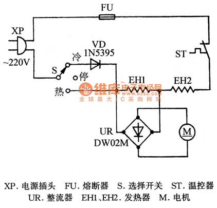
XP-plug; FU-fuse; ST-temperature controller; UR-rectifier; S-selection switch; M-motor; EH1,EH2-heater. (View)
View full Circuit Diagram | Comments | Reading(9896)
LM101, HA2-2520 multiplication circuit diagram
Published:2011/8/19 1:19:00 Author:Jessie | Keyword: multiplication
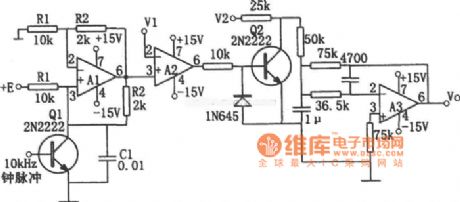
As shown in figure is multiplication circuit, A1 forms voltage controlled current source, A2 forms voltage comparator, A3 forms active low-pass filter. When time constant R1C1 equals to the clock pulse cycle, the relationship between input and output is: Vo=-V1V2/E. If make E=1V, thereare Vo=-V1V2, V1 and V2 required to be positive and limited in 10V, the V1 is slightly below E. Resistors R1, R2 and capacitor C1 require touse thecomponents withgoodtemperature stability. A1is HA2-2520, A2, A3choose LM101A. (View)
View full Circuit Diagram | Comments | Reading(854)
MC1496 multiplication circuit diagram
Published:2011/8/19 1:39:00 Author:Jessie | Keyword: multiplication
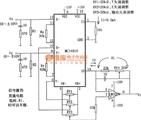
When the circuit selects Rx = 30kΩ, Ry = 62kΩ, I1 = 0.5mA, K = 1 / 10, the output voltage Vo is Vo = VxVy/10 Since the output current Io is inverted by inverting amplifier, so the X-Vx is added to x- end, this is because positive selection of the right side decision; if the right side is selected as negative, the input signal should be added to the X + side. In order to prevent parasitic oscillation, the input end of Vx and Vy is connected 470Ω 10pF network in series. (View)
View full Circuit Diagram | Comments | Reading(1236)
Buick headlamp circuit diagram(no DRL, with beam adjustment)
Published:2011/8/18 22:55:00 Author:Jessie | Keyword: Buick headlamp , no DRL, beam adjustment

View full Circuit Diagram | Comments | Reading(655)
Division circuit with MC1494 and LM307
Published:2011/8/18 1:10:00 Author:Jessie | Keyword: Division

This circuit's output voltage Vo is Vo=10Vz/Vx. The input signal Vx and Vz can be positive and negative, so this circuitis afour quadrant division circuit. Then the voltage-regulator diode in the output end of LM307N is the output voltage clamp diode when the input Vx decreases. (View)
View full Circuit Diagram | Comments | Reading(867)
TDA2822 Wireless headset circuit diagram
Published:2011/8/18 1:18:00 Author:Jessie | Keyword: Wireless headset

TDA2822-B Wireless headset is the voice tool for students to listen to electronic teaching pronunciation, the failure rate is higher. Because the relevant materialthat manufacturer offer is not neat,writter draw a diagram according to the real. TDA2822M is a double channel audio amplifier integrated circuit. Magnetic coil S receives the audio signal,and sends to integrated blockpin6 fromvolume potentiometer W center tap ,after internal amplification it is output by pin 3,then it isadded to two parallel headphonesby coupling capacitors C2 to makevoice. (View)
View full Circuit Diagram | Comments | Reading(4862)
PT2262/PT2272 Chip principle circuit diagram
Published:2011/8/18 1:20:00 Author:Jessie | Keyword: Chip principle
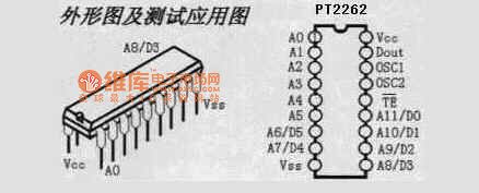
Application scope: vehicle anti-theft system, family security system, remote control toys, other appliances' remote controlling.
(View)
View full Circuit Diagram | Comments | Reading(2307)
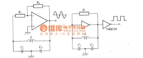
Colpitts oscillator circuit diagram
Published:2011/8/18 1:22:00 Author:Jessie | Keyword: Colpitts oscillator
View full Circuit Diagram | Comments | Reading(1422)
High-frequency high-voltage oscillator(DC voltage convertor) circuit diagram
Published:2011/8/18 1:23:00 Author:Jessie | Keyword: High-frequency high-voltage oscillator, DC voltage convertor

View full Circuit Diagram | Comments | Reading(1278)
Electronic voltage regulated electromagnetic vibration circuit diagram
Published:2011/8/18 1:29:00 Author:Jessie | Keyword: Electronic voltage regulated, electromagnetic vibration

View full Circuit Diagram | Comments | Reading(1072)
| Pages:515/2234 At 20501502503504505506507508509510511512513514515516517518519520Under 20 |
Circuit Categories
power supply circuit
Amplifier Circuit
Basic Circuit
LED and Light Circuit
Sensor Circuit
Signal Processing
Electrical Equipment Circuit
Control Circuit
Remote Control Circuit
A/D-D/A Converter Circuit
Audio Circuit
Measuring and Test Circuit
Communication Circuit
Computer-Related Circuit
555 Circuit
Automotive Circuit
Repairing Circuit