
Circuit Diagram
Index 500
Boiler induced draft fan circuit (2)
Published:2011/9/8 19:56:00 Author:TaoXi | Keyword: Boiler, induced draft fan

This circuit ensures the Y-△ decompression start has enough delta-time in the switching process. In the KM2 coil control circuit, you can connect two pairs of contact points in series to ensure the circuitto haveenough delta-time in the switching process.
(View)
View full Circuit Diagram | Comments | Reading(1108)
Incremental Photoelectric Encoder Basic Waveforms and Circuit
Published:2011/5/17 2:38:00 Author:Sharon | Keyword: Incremental, Photoelectric Encoder, Basic Waveforms
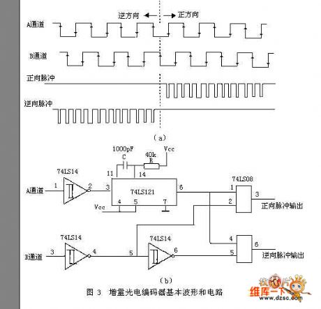
Incremental encoder is a sensor output pulse. Its encoder disk and resolution is much simpler and higher than those of the absolute encoder. Usually it only requires three code channels, where the code channels actually do not have the absolute meaning of the encoder code channel, but form the count pulse.Its encode disk external and middle channel have the same number of average-distributed transparent or no-transparent fan-shaped area (raster), and the two fan-shaped areas are separated by half-area. When the decode disc rotates, the output signal is pulse signal with 90 °phase shift of the A phase and B phase. And pulse signal has only a light slit produced by the third code channel (It acts as a basis of encoder disk and provides an initial zero signal for count).
The phase relationship of A and B two output signals (lead or lag) can determine the direction of rotation. Figure 3 (a) shows when the encoder disk rotates forward, A channel's pulse waveform is advanced than that of B channel by π / 2, while in reversal, A channel's pulse waveform legs behind that of B channel by π / 2. Figure 3 (b) is a real circuit, with the bottom of A channel's shaping wave triggering the monostable and generating positive pulse, and then touching with B channel's shaping wave. When the encoder disk rotates forward, only positive pulse outputs, otherwise, only the reverse pulse outputs.
(View)
View full Circuit Diagram | Comments | Reading(4215)
Mental state tester circuit diagram
Published:2011/9/8 3:50:00 Author:Lucas | Keyword: Mental state tester

People's emotional stress not only makes the human heart beat fast, and people's skin become wet. Because the skin becomes wet, its resistance becomes low, so that the test device reacts. Test bars and soft wires are wrapped around the fingers or wrist as a receiver, the output signal is amplified by IC1 and read out by μA meter and R3. μA middle indicates 0, then C1 suppresses hum. During the period of time, the skin resistance can determine people's general emotional state, which is indicated by the table connected to the E. IC2 forms the integrator to ensure that the circuit automatically adjusts the average skin resistance.
(View)
View full Circuit Diagram | Comments | Reading(1143)
ECG FM demodulator circuit diagram
Published:2011/9/8 20:51:00 Author:Lucas | Keyword: ECG FM demodulator
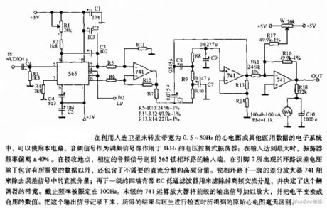
The circuit is suitable for satellite to transmit the ECG with bandwidth in 0.5 ~ 50Hz or other medical data in electronic systems. Audio signal is used as FM signal source applied to the 1KHz voltage controlled oscillator: when the input is maximum, the oscillator frequency deviation is ± 40%. In the receiving place, the corresponding audio signal is sent to the input of 565 PLL. The loop error voltage on pin 7 contains the necessary, in addition, it also contains the DC components and high-frequency components which are not necessary.
(View)
View full Circuit Diagram | Comments | Reading(3096)
An easy thermostat circuit composed of intelligent temperature sensor LM75 based on I2C Bus
Published:2011/9/8 5:38:00 Author:Felicity | Keyword: thermostat circuit, easy, intelligent temperature sensor

The figure shows an easy thermostat circuit composed of intelligent temperature sensor LM75 based on I2C Bus. LM75 drives the relay coil through 2N3904 transistor according to the test temperature to control the power supply of the thermostat to achieve thermostatic control. (View)
View full Circuit Diagram | Comments | Reading(1538)
Typical application of 7-way intelligent temperature sensor MAX6697
Published:2011/9/8 8:25:00 Author:Felicity | Keyword: 7-way, intelligent temperature sensor

The figure shows the typical application circuit of 7-way intelligent temperature sensor MAX6697. MAX6697 matches 6 temperature measurement transistor (VT1~VT6). The transistors collector is closed to act as diode. VT1,VT6 are used to detect the chip temperature of CPU and GPU.C1~C6 and transistor in parallel can filter out the high frequency disturbance on the signal bus.C7 is power decoupling capacitor. R1~R4 are pull-up resistors.MAX6697 can connect to microprocessor (μP) through SMbus.
(View)
View full Circuit Diagram | Comments | Reading(828)
The low voltage logic circuit composed of intelligent temperature sensor TMP03
Published:2011/9/8 5:07:00 Author:Felicity | Keyword: low voltage logic circuit , intelligent temperature sensor

It’s convenient to drive logic gates under low voltage with the collector open. The low voltage logic circuit is shown in the figure. The DOUT terminal of TP03 connects to the +3.3V power through the 3.3kΩ pull-up resistor and the current through R is about 1mA. The output voltage of TMP03 is put on the input terminal of the low voltage logic gate. This circuit adapts +3.3V systems. (View)
View full Circuit Diagram | Comments | Reading(686)
Starlike multidrop parallel connection three-phase electromotor winding open circuit checking circuit
Published:2011/9/8 20:31:00 Author:Christina | Keyword: Starlike, multidrop, parallel connection, three-phase, electromotor, winding, open circuit, checking circuit

The stator windings of the three-phase electromotor which is more than 10KW always use the varnished wire parallel winding and the Multidrop parallel connection. In one phase winding, if one or more wires cut off, you are difficult to judge by using the light, you can use the three-phase current balance method. The circuit is as shown in the figure, it uses the single-phase AC arc welding machine transformer T as the power supply, the three ammeters A1, A2 and A3 are connected with the U1, V1 and W1 respectively. After the power is connected, you can observe the current values of the three ammeters. In normal condition, the values are different.
(View)
View full Circuit Diagram | Comments | Reading(1424)
Using twisted pair to transmit temperature signal (low power programmable integrated temperature controller TMP01)
Published:2011/9/8 9:17:00 Author:Felicity | Keyword: twisted pair, temperature signal, low power, programmable integrated temperature controller

The output signal output by Pin 5 of TMP01 is analog voltage which can be easily disturbed during transmission in industrial sites. Then twisted pair can be adopted as shown in the figure. Firstly using OP297 split Uo into two-way signal and then transmitted through twisted pair and finally received and restored by AMP03. The differential amplifier composed by AMP03 can reduce the noise voltage as 95dB besides amplify the temperature signal. After restoration the lossless voltage signal Uo can be achieved.
(View)
View full Circuit Diagram | Comments | Reading(715)
Rotating monitor circuit
Published:2011/9/8 20:20:00 Author:Christina | Keyword: Rotating monitor

This circuit can be used to monitor the rotation of the mechanical part, the transmitter uses the approach switch AS. When the mechanical part is rotating, the switch cuts off the oscilation circuit through the gap. The approach switch AS can be used as the variable resistor which is connected with the voltage divider circuit, the fulcrum of the voltage divider circuit is connected with the Schmidt trigger, the trigger can make the square-wave voltage have the rising edge and the down edge, the hysteresis loop can produce the disturbance voltage. The left transistor's collector electrode of the Schmidt trigger is connected with the base electrode of the next transistor through the RC.
(View)
View full Circuit Diagram | Comments | Reading(798)
Celsius or Fahrenheit temperature conversion circuit composed of cheap current output integrated temperature sensor TMP17
Published:2011/9/8 8:40:00 Author:Felicity | Keyword: temperature conversion, current output, output integrated temperature sensor

(View)
View full Circuit Diagram | Comments | Reading(920)
Broadband drive for capacitive load composed of LM6361
Published:2011/9/8 7:09:00 Author:Felicity | Keyword: Broadband drive, capacitive load


View full Circuit Diagram | Comments | Reading(1101)
Gain Programmable Amplifier Circuit
Published:2011/9/8 7:03:00 Author:Felicity | Keyword: gain programmable, amplifier
View full Circuit Diagram | Comments | Reading(758)
Lithium battery quick charger composed of LM3420-8.4
Published:2011/9/8 7:02:00 Author:Felicity | Keyword: Lithium battery, quick charger

This circuit adopted the specialized lithium battery charger LM3420-8.4 and it’s simple and have high performance and can charges two lithium batteries quickly. When the charging voltage reaches the rated value (with a single lithium battery it’s 4.2V), the charging current drops down to avoid permanent damage of lithium battery caused by overvoltage.
(View)
View full Circuit Diagram | Comments | Reading(2038)
Circuit of gain programmable amplifier composed of OPA676
Published:2011/9/8 6:37:00 Author:Felicity | Keyword: gain programmable, amplifier

View full Circuit Diagram | Comments | Reading(594)
An amplifier with gain controlled by frequency(LTC1043)
Published:2011/9/8 6:35:00 Author:Felicity | Keyword: amplifier, gain controlled by frequency

View full Circuit Diagram | Comments | Reading(703)
A isolation amplifier composed of ISO122 with programmable gain
Published:2011/9/8 6:30:00 Author:Felicity | Keyword: isolation amplifier, programmable gain

View full Circuit Diagram | Comments | Reading(944)
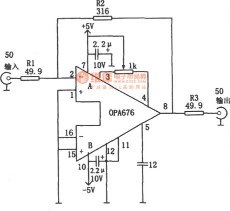
Broad Band Vedio Amplifier with 50Ω Input/Output Impedance (OPA676)
Published:2011/9/8 6:25:00 Author:Felicity | Keyword: Broad Band, Vedio Amplifier
View full Circuit Diagram | Comments | Reading(916)
Application of PWM-based Switching-Regulator Power Controller SG3524
Published:2011/9/8 6:20:00 Author:Felicity | Keyword: PWM, Switching-Regulator, Power Controller

View full Circuit Diagram | Comments | Reading(8256)
Boosting Switching-Regulator Power Circuit Composed of 555
Published:2011/9/8 6:14:00 Author:Felicity | Keyword: Boosting, Switching-Regulator Power Circuit

In the circuit, BG1 is the switch-adjusting transistor; operational amplifier IC1 composes the comparison amplifier; 555 time-base circuit is connected as astable multivibrator. The saw-wave voltage produced by the oscillator on C1 (Vmin=1/3Vz, Vmax=2/3Vz, the frequency determined by W1 and C1) is put onto the noninverting-terminal of the comparison amplifier IC1 and the sampling voltage is put onto the inverting-terminal of the comparison amplifier. (View)
View full Circuit Diagram | Comments | Reading(3142)
| Pages:500/2234 At 20481482483484485486487488489490491492493494495496497498499500Under 20 |
Circuit Categories
power supply circuit
Amplifier Circuit
Basic Circuit
LED and Light Circuit
Sensor Circuit
Signal Processing
Electrical Equipment Circuit
Control Circuit
Remote Control Circuit
A/D-D/A Converter Circuit
Audio Circuit
Measuring and Test Circuit
Communication Circuit
Computer-Related Circuit
555 Circuit
Automotive Circuit
Repairing Circuit