
Circuit Diagram
Index 484
Regulator DC-DC Circuit and Pin of Power Supply Monitor and its Main Features-MAX624
Published:2011/9/13 3:01:00 Author:Zoey | Keyword: Regulator, DC-DC Circuit, Binary output Converter
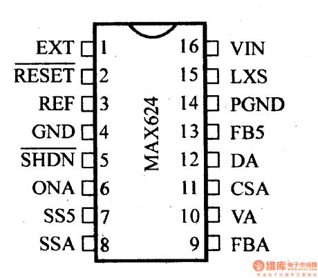
Switching frequency of MAX624 binary output DC-DC converter is 1MHz, working voltage range is 3.0~5.0V, static working current is 0.5mA, power-off current is 40µA. When the working turns to 5V, efficiency of SMPS will be 85%, input voltage 3V~5.5V, output voltage 5V±4%, output current 200mA, auxiliary output voltage 12V±2%. (View)
View full Circuit Diagram | Comments | Reading(736)
Regulator DC-DC Circuit and Pin of Power Supply Monitor and its Main Features-MAX638
Published:2011/9/13 2:45:00 Author:Zoey | Keyword: Regulator, DC-DC Circuit, CMOS, Buck Converter
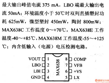
MAX638 CMOS DC-DC buck converter is a switched regulator, it has a interior MOS FET that has a peak of 375mA, this FET can constitute a DC-DC converter. Its voltage output can be adjusted by external resistance. For this converter, typical efficiency is 85%, typical static current 135µA, oscillation frequency 65kHz. Maximum voltage of LX terminal and LBO terminal is 18V, peak of output current of LX is 375mA, LBO 50mA. If room temperature drops to below 50℃, power of DIP platic encapsulation will be 625mW, micro platic encapsulation will be 450mA, and ceramic encapsulation 800mW. Working temperature range of MAX638 is 0~+70℃, MAX638 -40~+85℃, MAX638M -55~+125℃. This converter has an interior circuit for input voltage-detection. (View)
View full Circuit Diagram | Comments | Reading(735)
RegulatorDC-DC Circuit and Pin of Power Supply Monitor and its Main Features
Published:2011/9/13 0:22:00 Author:Zoey | Keyword: Regulator, DC-DC Circuit, Pin of Power Supply Monitor, Main Features
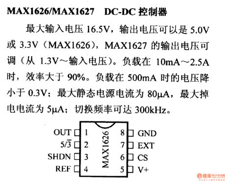
The maximum input voltage of MAX1626/MAX1627 DC-DC controller is 16.5V, output voltage of MAX1626 can be 5.0V or 3.3V,while output voltage of MAX1627 can be adjusted from 1.3V to itsinput voltage. If the load is between 10mA to 2.5A, efficiency will exceed 90%. Voltage will descend to below 0.3V when the load ranges from 10mA to 2.5A. The maximum static current of the power supply is 80µA, the maximum power-off current is 5µA. The Switched frequency can be as large as 300kHz. (View)
View full Circuit Diagram | Comments | Reading(823)
Regulator DC-DC Circuit and Pin of Power Supply Monitor and its Main Features-MAX608
Published:2011/9/13 3:02:00 Author:Zoey | Keyword: Regulator, DC-DC Circuit, Power supply, High-efficiency Controller
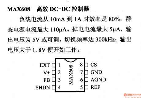
Ifload current of MAX608 high-efficiency DC-DC controller ranges from 10mA to 1A, its efficiency will be 80% and static current of power supply will be 110µA. For this controller, the maximum power-off current is 5µA, output voltage is 5V or adjustable, the switching frequency can reach 300kHz. This controller will begin towork as soon as voltage exceed 1.8V.
(View)
View full Circuit Diagram | Comments | Reading(751)
Regulator DC-DC Circuit and Pin of Power Supply Monitor and its Main Features-MAX606/MAX607
Published:2011/9/13 3:02:00 Author:Zoey | Keyword: Regulator, DC-DC Circuit, Pin of Power Supply Monitor, step-up converter
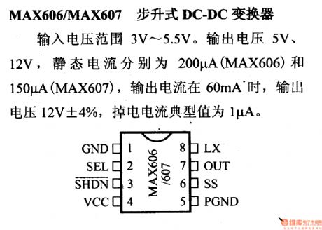
The input voltage range of MAX606/MAX607 step-up converter is 3V~5.5V. Its output voltage is 5V or 12V. Static current of MAX606 is 200µA and MAX607 is 150µA. If output current reaches 60mA, output voltage will turn to be 12V±4%. Typical value of its power-off current is 1µA. (View)
View full Circuit Diagram | Comments | Reading(683)
Regulator DC-DC Circuit and Pin of Power Supply Monitor and its Main Features-MAX603/MAX604
Published:2011/9/13 2:49:00 Author:Zoey | Keyword: Regulator, DC-DC Circuit, Pin of Power Supply Monitor, Linear Regulator
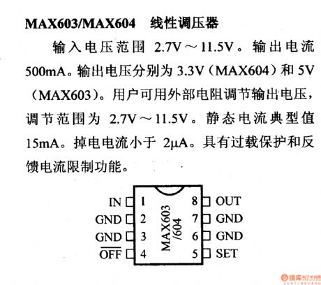
The input voltage range of MAX603/MAX604 linear regulator is 2.7V~11.5V. Its output current is 500mA, output voltage of MAX604 is 3.3V, MAX603 5V. External resistance regulator can be used to adjust output voltage, the adjusting range is 2.7V~11.5V. Typical value of static current is 15mA, power-off current is 2µA.This regulator has such functions as overload-proof and restrictions on feedback current. (View)
View full Circuit Diagram | Comments | Reading(1390)
Regulator DC-DC Circuit and Pin of Power Supply Monitor and its Main Features-MAX736/737 Regulator
Published:2011/9/13 2:32:00 Author:Zoey | Keyword: Regulator, DC-DC Circuit, Pin
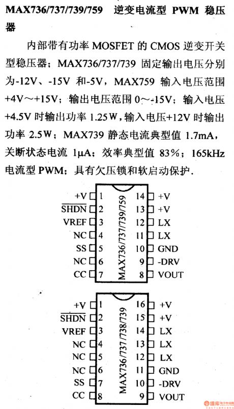
The MAX736/737/739/759 PWM regulator refers to the CMOS countercurrent switched regulator that has an interior power MOSFET. Fixed output voltage of MAX736/737/739 are -12V,-15V and -5V respectively. Input voltage range of MAX759 is +4V~+15V, output voltage range is 0~+15V. If the input voltage is +4.5V, output power will be 1.25W, and when it ascends to +12V, output power will be 2.5W. Typical value of static current of MAX739 is 1.7mA. In a power-off state, the current is 1μA. Typical value of efficiency is 83%. 156-kHz current PWM has an undervoltage lock and a soft-start protection device.
(View)
View full Circuit Diagram | Comments | Reading(722)
Regulator DC-DC Circuit and Pin of Power Supply Monitor and -MAX672/673 Reference Voltage Circuit
Published:2011/9/13 2:34:00 Author:Zoey | Keyword: Regulator, DC-DC Circuit, Reference Voltage Circuit
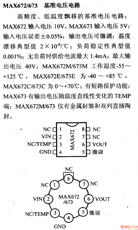
MAX672/673 reference voltage circuit (+10V) has thefeatures such as high accuracy, low temperature drift. Input voltage of MAX672 is 10V, of MAX673 is 5V. For this circuit, the input voltage error ±0.05% and output voltage can be adjusted slightly. The typical temperature drift is 2×10⁻⁶/℃, typical value of stable load is 0.001%, and no-load maximum input current is 1.4mA. The maximum output voltage is 40V. Working temperature of MAX672M/673M is -55~+125℃, MAX672E/673E -40~+85℃,. MAX672C/673C 0~+70℃.. The circuit itself has an interior short-circuit-proof circuit. Output voltage of TEMP terminal of MAX673 linearly changes with temperature. For MAX672M/673, only metal encapsulation and DIP ceramic encapsulation are available. (View)
View full Circuit Diagram | Comments | Reading(692)
Toy model sign indication circuit
Published:2011/9/12 21:17:00 Author:John | Keyword: Toy model sign indication


The circuit is generally set in a variety of junctions or corners, aiming to indicate the direction for the toy train or car. The main direction is to rely on its successive group of light-emitting diodes, as shown.
IC14017 is the decimal count splitter, which has five output named Q0~Q4 while only 4 is used to form the quaternary count distributor. N1~N5 are 5 Schmitt triggers. N1 is the oscillator to provide IC1’s clock source. N2 ~ N5 5 are 4 monostable triggers. T1~T4 are the drive circuit for light-emitting diode.
(View)
View full Circuit Diagram | Comments | Reading(995)
Regulator DC-DC Circuit and Pin of Power Supply Monitor and its Main Features-MAX864 Converter
Published:2011/9/13 2:18:00 Author:Zoey | Keyword: Regulator, DC-DC Circuit, Pin, Converter
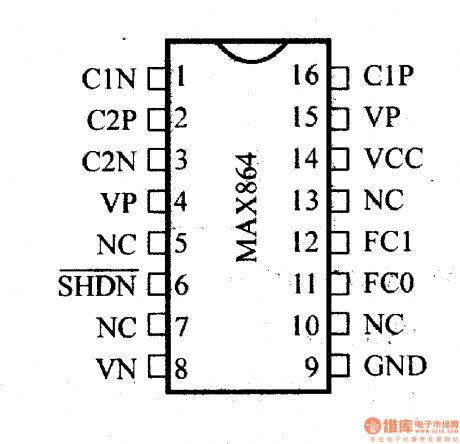
MAX864 dual-output voltage pump charging converter can input 1.5V~6.2V voltage. When input voltage ascends to 3V, the converter will get ±6.0-V output voltage. And when it ascends to 5.0V, it will get ±10-V output voltage. The output current is 10mA, and the switching frequency can be 5kHz, 30kHz, 100kHz or 200kHz. Its static current is 200µA.This converter only needs four 1-µF external capacitors. (View)
View full Circuit Diagram | Comments | Reading(751)
Thermocouple temperature system simulation circuit
Published:2011/9/12 21:17:00 Author:John | Keyword: Thermocouple temperature system

Temperature on the cold junction is measured by the use of resistance temperature detectors (RTD) or thermistor (shown in the RT). The resistance for these two devices changes along with the temperature. On-chip current source provides the required excitation current. In this measurement configuration, a ratio is used, that is, the ADC reference voltage source and the precision resistor use the same excitation current. A ratio configuration enables the temperature measurement on the cold junction to be independent from the excitation current, because the change of excitation current can lead to same changing amount of the voltage generated by the sensor and that generated by the precision resistor. Therefore, there is no effect on analog digital conversion. (View)
View full Circuit Diagram | Comments | Reading(2118)
Regulator DC-DC Circuit and Pin of Power Supply Monitor and its Main Features-MAX865 Converter
Published:2011/9/13 2:12:00 Author:Zoey | Keyword: Regulator, DC-DC Circuit, Pin of Power Supply Monitor, Converter
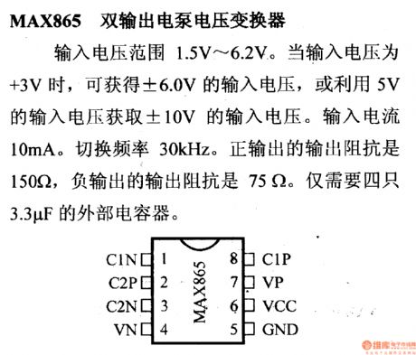
MAX865 dual-output voltage pump converter can input 1.5V~6.2V voltage. When the input voltage ascends to +3V, the converter will get ±6.0-V input voltage, or it will get ±10-V input voltage by using 5-V input voltage. The input current is 10mA, and the switching frequency is 30kHz. Impedance of positive output is 150Ω, while impedance of negative output is 75Ω. This converter only needs four 3.3-µF external capacitors.
(View)
View full Circuit Diagram | Comments | Reading(709)
Simple current limiting circuit
Published:2011/9/12 21:59:00 Author:John | Keyword: current limiting
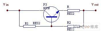

When the current is less than the value set, the bias current provided by R1 leads the P3 to be saturated to conduct. And it can not afford to control the current. When the current is greater than or equal to the set value, the pressure drop on R would increase and be close to the pressure drop of R2 after acrossing the transistor junction. Then it can limit the current through P3 in order to limit the current to a certain level. If R2 is used as a regulator instead, the limiting performance can be more accurate. The drawback of the introduced protection circuit is that the pressure drop can be all down on the transistor when the current is overload, especially a short circuit. Thus, it would lead to certain power consumption.
(View)
View full Circuit Diagram | Comments | Reading(7084)
Regulator DC-DC Circuit and Pin of Power Supply Monitor and Reverse DC-DC Converter
Published:2011/9/13 2:22:00 Author:Zoey | Keyword: Regulator, DC-DC Circuit, Pin of Power Supply Monitor, RP
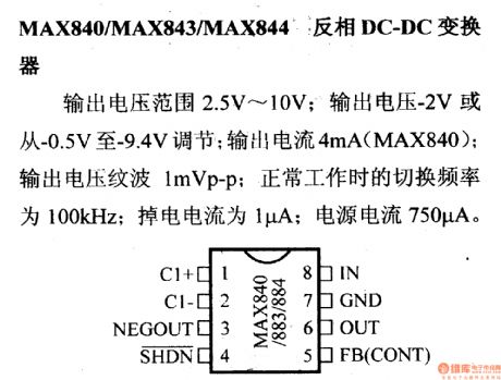
Voltage output of MAX840/MAX843/MAX844 RP DC-DC converters ranges from 2.5V to 10V. The output voltage can be adjusted to -2V or -0.5V~-9.4V. Output current of MAX840 is 4mA and output voltage wave is 1mVp-p. In normal operation, the switching frequency is 100kHz, the power-off current is 1µA and current of power supply is 750µA. (View)
View full Circuit Diagram | Comments | Reading(874)
NISSAN new Teana audio (with navigation system) circuit(e)
Published:2011/9/12 22:00:00 Author:John | Keyword: navigation system, new Teana audio
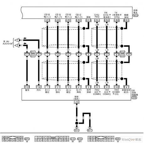
NISSAN new Teana audio (with navigation system) circuit is shown.
(View)
View full Circuit Diagram | Comments | Reading(858)
incandescent light life extension switch circuit
Published:2011/9/12 22:02:00 Author:John | Keyword: incandescent light, extension switch

Incandescent light’s filament is with large thermal resistance and very small cold resistance. So at the moment of opening light, the impact current flowing through the filament is very large. It can be very easy to make the filament burn within damages. Life extension’s switch can be a good solution to this problem, just as shown in the figure.It can effectively extend lamp’s life greatly. When switch S is connected, the voltage across the capacitor can not change suddenly and the voltage across C is zero. The thyristor VT deadlines without triggering voltage. At this moment, the current flowing through the bulb E is the half-wave current rectified by VD2. The light bulb is pre-heated with darkness and the inrush current is very small.
(View)
View full Circuit Diagram | Comments | Reading(1446)
Theory of Land Cruiser 70 Light Cross-country Car Engine Control and its Ignition
Published:2011/9/12 23:52:00 Author:Zoey | Keyword: Land Cruiser, 70 Light Cross-country Car, Engine Control, Ignition
Figure: Theory of Land Cruiser 70 Light Cross-country Car Engine Control, Ignition (22R-E,22R motor)
13 a fuel injector; 14 an electronic fuel injection systems (EFI) Main relay; 15 - fuel pump relay; 16 a fuel pump motor; 17 a knock sensor; 18 an oxygen sensor; 19 an air flow meter; 20 a fault detection socket; 21 - valve fuel pressure increases; 22 an air injection system valve; 23 an engine electronic control unit (ECU); 24 an engine warning light detection; 25 a coolant temperature sensor; 26 a throttle position sensor; 27 point fire coil; 28 point fire module (electronic components); 29 a distributor (22R-E engine); 30 A contact-type distributor (22R engine); 31,40 a - anti-interference filter; 92 a speed sensor; 113 a brake light switch; 69 a combination of dashboard 6C terminal (tachometer); 69-7D - four-wheel drive indicator light (View)
View full Circuit Diagram | Comments | Reading(788)
An Application Circuit of Transistor Array
Published:2011/9/13 0:06:00 Author:Zoey | Keyword: Transistor Array , Application Circuits
Here is the picture that presents the application circuits of Transistor Array (View)
View full Circuit Diagram | Comments | Reading(771)
STK392-040 Thick Film Power Amplifier Integrated Circuit Diagram
Published:2011/9/13 0:09:00 Author:Zoey | Keyword: Thick Film, Power Amplifier , Integrated Circuit Diagram
(View)
View full Circuit Diagram | Comments | Reading(670)
TX05C-R infrared surveillance alarm circuit
Published:2011/9/12 22:03:00 Author:John | Keyword: infrared surveillance alarm

TX05C-R infrared surveillance alarm circuit is shown. It can be used for surveillance of walls, windows, doors and various restricted areas. If someone breaks into or over the alarm position, it will sound to play a security role. The circuit consists of transmitter module, receiver module, time-base circuit, power circuit, the speaker and other parts. And the power supply circuit is formed by the transformer T, rectifier diodes, three-terminal voltage regulator integrated circuit A4 and other parts. It can output 12V DC voltage to power the entire circuit. (View)
View full Circuit Diagram | Comments | Reading(1789)
| Pages:484/2234 At 20481482483484485486487488489490491492493494495496497498499500Under 20 |
Circuit Categories
power supply circuit
Amplifier Circuit
Basic Circuit
LED and Light Circuit
Sensor Circuit
Signal Processing
Electrical Equipment Circuit
Control Circuit
Remote Control Circuit
A/D-D/A Converter Circuit
Audio Circuit
Measuring and Test Circuit
Communication Circuit
Computer-Related Circuit
555 Circuit
Automotive Circuit
Repairing Circuit