
Circuit Diagram
Index 494
the power supply of A3(A4)
Published:2011/8/20 2:20:00 Author: | Keyword: power supply

View full Circuit Diagram | Comments | Reading(869)
the radiation detector (CD4011)
Published:2011/9/8 6:22:00 Author:Ariel Wang | Keyword: radiation

It is the radioactive beam monitor circuit.It consists of radiation testing sensor,two input ends and four NOT-AND gates.It could be used to detect ray α、γ、β and X.It has high sensibility.When low-level radiation detected,the detector will give out alarm sound every now and then.When the radiation is over standard,it will give out alarm sound constantly.
(View)
View full Circuit Diagram | Comments | Reading(1586)
The multifunction physiotherapy
Published:2011/9/8 6:17:00 Author:Ariel Wang | Keyword: multifunction , physiotherapy

The multifunction physiotherapy circuit is shown as the chart.Its electrical stimulation pulse frequency could increase(or decrease) from 2 to 256Hz.Every frequency it could last 8s.It transforms automaticly.It works in cycle.
(View)
View full Circuit Diagram | Comments | Reading(1633)
The Transistor Characteristic Curve Drawer Circuit Composed of 555
Published:2011/9/6 4:44:00 Author:Felicity | Keyword: Transistor Characteristic Curve Drawer

The circuit shown in figure one consists of sawtooth wave generator and step wave generator.To draw the transistor characteristic curve two kind of voltage are needed. First is the step wave that put on pole b to generate different base current.Second the sawtooth wave that put on pole c, its periodic time corresponding to the step wave to draw the transistor output characteristic curve,the Ic-Vce characteristic curve.The sawtooth generator consists of multivibrator (IC(555)、R1、R2、C1) and intergrator(C2,R3).And the oscillation frequency of the multivibrator is f=1.44/(R1+2R2)C1. (View)
View full Circuit Diagram | Comments | Reading(1418)
The Power Frequency Noise Filter Circuit (μPC822)
Published:2011/9/6 4:44:00 Author:Felicity | Keyword: Power Frequency Noise Filter

The circuit is a double-T filter to filter out the mixed 50Hz (or 60Hz) power frequency noise when amplifying (such as sensor )weak signal.If only using the RC components to comprise similar filter, usually the value of Q is low and has the attenuation performance of the bandwidth performance .Adopting operational amplifier and positive feedback can increase the value of Q. Supposing that the values of Q is Q', then Q'=Q/(1一K),and K=RA/(RA+RB).Tuning the coefficient Q can increase the value of Q.And the resonant frequency of the circuit is fo=1/2πRC and the positive feedback components are R/2 and 2C. (View)
View full Circuit Diagram | Comments | Reading(2030)
The fruits and vegetables detoxification machine
Published:2011/9/8 6:16:00 Author:Ariel Wang | Keyword: fruits, vegetables, detoxification

The fruits and vegetables detoxification machine uses ozone to do the sterilization and degradation on the pesticides remainings in fruits and vegetables.The circuit is made up of power supply circuit,electronic timer, relay-driven circuit,air pump,high voltage generator and ozone generator.The AC220V commercial power gives power supply to the air pump and high voltage generator.It is reduced by T1,commutated by VD1~VD4,filtered by C1.Then it generates about 12V DC voltage for the use of relay-driven circuit.The 12V voltage is regulated by KA78L05 through IC1.Then it forms 5V steady voltage for electronic timer circuit.
(View)
View full Circuit Diagram | Comments | Reading(1629)
the acupoint detector composed of 555
Published:2011/9/8 6:16:00 Author:Ariel Wang | Keyword: acupoint detector

It is the acupoint detector circuit.The acupoint detector is made up by the detecting electrode A and B,multivibrator and acoustic-optic indicator. The oscillator composed of IC1,R8,R9 and C1 output the signal(square wave).The signal is controlled by the oscillator composed of IC2,R11,R12 and C3.Because the impedances in acupoint and non-acupoint act differently in human beings.The circuit converts the impendances to different potentials. The oscillation frequency of the oscillator emits different acoustic-optical signals.In this way,it realizes the acupoint detection.
(View)
View full Circuit Diagram | Comments | Reading(1243)
the relaxation oscillation circuit with 300MHZ frequency modulation
Published:2011/9/8 6:16:00 Author:Ariel Wang | Keyword: relaxation oscillation , 300MHZ, frequency modulation
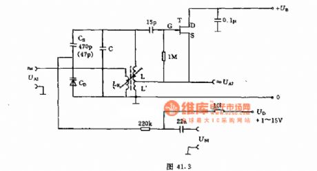
The oscillation circuit signals come from UA2 or UA1.LK is one turn within 300MHZ.L' is about 10% of L's turns.You can do frequency fine adjustment to UD using varactor CD.And you can do frequency modulation to UNF.If you want to choose the capacitor CS,you can refer to the frequency range and the varactor based on the frequency offset required.The capacitor C in oscillating circuit can be chosen as the way above.
(View)
View full Circuit Diagram | Comments | Reading(972)
OPA603 Constituted Low-pass Filter Circuit Of 10MHz
Published:2011/8/12 4:54:00 Author:Felicity | Keyword: Low-pass Filter, 10MHz

The circuit is showed in the picture. The circuit makes use of Second-order Butterworth low-pass filter. The fillter is made of high-speed current feedback operational amplifier OPA603 with broadband of 100MHZ. The transition frequency is f0=1/2πRC. The parameter is showed in the picture.f0=10MHz. Circuit gain is 1.6.
(View)
View full Circuit Diagram | Comments | Reading(1335)
0~16 Hours Stepless Timing Controller Circuit (NE555, CD4040)
Published:2011/9/6 4:45:00 Author:Felicity | Keyword: Stepless, Timing Controller
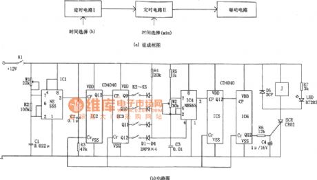
This controller consists of two stage timer and driver. Timing circuit 1 consists of IC1(555) and two 12 bit binary counter/frequency divider IC2 and IC3(CD4040) to produce totally 16 adjustable timing signal as:0,1,2......14,15hour(s). Timing circuit Ⅱwhich is controlled by timing circuit I consists of IC4(555) and two 12 bit binary counter/frequency divider IC5 and IC6(CD4040) .Timing circuit controls timing circuit Ⅱby the reset terminal of IC4 and timer I can produce 0~60 minutes continuously adjustable timing signal. (View)
View full Circuit Diagram | Comments | Reading(2309)
the absolutely useful switch power supply:the Kaige 4C7108 power supply(A4)
Published:2011/8/20 2:22:00 Author: | Keyword: absolutely useful , switch power supply

View full Circuit Diagram | Comments | Reading(998)
the absolutely useful switch power supply:the SONY KV2185 power supply(A4)
Published:2011/8/20 2:22:00 Author: | Keyword: absolutely useful , switch power supply

View full Circuit Diagram | Comments | Reading(812)
the absolutely useful switch power supply:the SONY KV2184 power supply(A4)
Published:2011/8/20 2:21:00 Author: | Keyword: absolutely useful, switch power supply

View full Circuit Diagram | Comments | Reading(1076)
the absolutely useful switch power supply:the sony F29 power supply(A4)
Published:2011/8/20 2:21:00 Author: | Keyword: absolutely useful , switch power supply

View full Circuit Diagram | Comments | Reading(754)
the absolutely useful switch power supply:the Ix0689 power supply(A4)
Published:2011/8/20 2:21:00 Author: | Keyword: absolutely useful , switch power supply

View full Circuit Diagram | Comments | Reading(861)
the absolutely useful switch power supply :the D2902 power supply(A4)
Published:2011/8/20 2:21:00 Author: | Keyword: absolutely useful, switch power supply

View full Circuit Diagram | Comments | Reading(779)
the absolutely useful switch power supply :the C7458 power supply(A4)
Published:2011/8/20 2:21:00 Author: | Keyword: absolutely useful , switch power supply

View full Circuit Diagram | Comments | Reading(819)
Circuit For Driving A Three-wire Fan (Smart Remote Thermal Fan Controller ADT7460)
Published:2011/9/6 4:45:00 Author:Felicity | Keyword: Driving A Three-wire Fan, Smart Remote, Thermal Fan, Controller


Driven by FET
(View)
View full Circuit Diagram | Comments | Reading(933)
Current Follower Configuration Of High Precision And Low Bias(LM11,LF351)
Published:2011/9/6 4:46:00 Author:Felicity | Keyword: Current Follower Configuration, High Precision, Low Bias

View full Circuit Diagram | Comments | Reading(1206)
20MHz Low-noise Broadband Amplifier
Published:2011/9/6 4:47:00 Author:Felicity | Keyword: 20MHz, Low-noise, Broadband Amplifier

View full Circuit Diagram | Comments | Reading(797)
| Pages:494/2234 At 20481482483484485486487488489490491492493494495496497498499500Under 20 |
Circuit Categories
power supply circuit
Amplifier Circuit
Basic Circuit
LED and Light Circuit
Sensor Circuit
Signal Processing
Electrical Equipment Circuit
Control Circuit
Remote Control Circuit
A/D-D/A Converter Circuit
Audio Circuit
Measuring and Test Circuit
Communication Circuit
Computer-Related Circuit
555 Circuit
Automotive Circuit
Repairing Circuit