
Circuit Diagram
Index 487
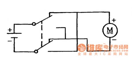
DC motor forward/reverse circuit controlled by the double pole double throw switch
Published:2011/8/25 7:40:00 Author:Nancy | Keyword: DC motor, forward/reverse circuit, double pole double throw switch
View full Circuit Diagram | Comments | Reading(3116)
The simplest multivibrator circuit composed of the photocoupler
Published:2011/8/25 7:39:00 Author:Nancy | Keyword: multivibrator , photocoupler
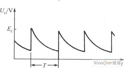
The figure1 is the simplest multivibrator circuit composed by the photocoupler. When the power is on, because the voltage across C can't break and the value of R is greater than RL, the power supply Ec is mainly added on the R, the electric potential at point F is very low, LED is at off state, with the charging voltage of capacitor increasing, the electric potential at point F is increasing gradually to a certain value to make LED conduct and flash, and make phototriode conduct and saturate, the output voltage jumps close to the power supply, but the left charge of the capacitor discharges quicky through phototriode and LED. (View)
View full Circuit Diagram | Comments | Reading(585)
8-Channel Digital Display Responder Composed of CH233 And 74LS273
Published:2011/8/25 7:41:00 Author:Sue | Keyword: 8-Channel, Digital Display, Responder

The picture shows the 8-channel digital display responder which is composed of CH233 and 74LS273. (View)
View full Circuit Diagram | Comments | Reading(2507)
Logic Display Pen Circuit with 4 States Composed of CD4511
Published:2011/8/25 7:48:00 Author:Sue | Keyword: Logic Display Pen, 4 States

The picture shows the logic display pen circuit with 4 states composed of CD4511. (View)
View full Circuit Diagram | Comments | Reading(4223)
Voltage Control Oscillator with Automatic Trace-Frequency-Way Composed of MC34025P
Published:2011/8/25 7:48:00 Author:Sue | Keyword: Voltage Control, Oscillator, Automatic Trace-Frequency-Way

The picture shows the voltage control oscillator with automatic trace-frequency-way composed of MC34025P. The circuit can be used as voltage control oscillator with automatic trace-frequency-way in ultrasonic oscillator. The output circuit of the ultrasonic oscillator is half-bridge way, so the power integrated circuit uses MC34025P which is two-phase output.
MC34025P has a wide oscillation frequency which is between 15 to 50KHZ. The center frequency is set by RP1, RP2. RP3 sets duty ratio which can prevent the push-pull switch circuit's two transistors from being connected at the same time. (View)
View full Circuit Diagram | Comments | Reading(1046)
Four-order Low-pass Filter Circuit without Capacity Cell
Published:2011/8/25 7:48:00 Author:Sue | Keyword: Four-order, Low-pass, Filter, without Capacity Cell

The picture shows the four-order low-pass filter circuit without capacity cell. (View)
View full Circuit Diagram | Comments | Reading(592)
Light-operated Automatic Scintillating Road Signal Lamp Circuit Composed of 555
Published:2011/8/25 7:48:00 Author:Sue | Keyword: Light-operated, Automatic Scintillating, Road Signal Lamp

The picture shows the light-operated scintillating road signal lamp circuit. The circuit consists of voltage reduction and rectification circuit, light-operated switch, 555 multivibrator, among which the voltage reduction and rectification circuit provides the whole circuit with direct current voltage.
In the circuit, BG is 3DU-type photosensitive triode. In the daytime, when there is light, BG's terminal voltage is small(1.6v) which will make power tube TWH8778 disconnected because of pin 5's low level. Then multivibrator doesn't work correspondingly and silicon controlled rectifier SCR is not connected. The lamp ZD is not illuminated. When it is dark, the photosensitive tube's inner resistance value becomes higher and even broken. TWH8778 is connected because of pin 5's high level(1.6V) which will make 555 oscillator begin to work because of the connection of the power circuit. (View)
View full Circuit Diagram | Comments | Reading(1075)
Ward Caller Five
Published:2011/8/12 1:43:00 Author:Felicity | Keyword: Ward Caller
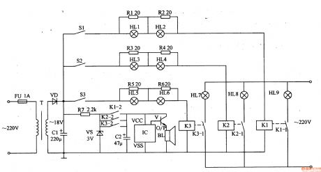
Work of the circuit
The circuit consists of power circuit, triggers control circuit and the acousto-optic call circuit. (It is showed in picture 9-88.)
Power circuit consists of fuse FU, power transformer T, rectifier diode VD, filter capacitor Cl, limiting resistor R7 and zener diode VS.
Triggers control circuit consists of Sl-S3 (ward bedside switch), resistors Rl-R6 and light HLl-H calendar and relay Kl-K3.
The acousto-optic call circuit consists of light HU-HLg, KI-K3 normally open contact, capacitor C2, music integrated circuit IC, transistor V, and the speaker BL.
This ward caller consists of power supply circuit ,trigger-control circuit and acousto-optic calling circuit.
When S1-S3 are not pressed, HL1-HL9 are all off and BL is noiseless. When one of S1-S3 is pressed, the relay in this branch closes, and the indicator is on. At the same time IC is power on and the music electrical signal output by O/P is amplified by V to drive BL to send out music sound. For example while S2 is pressed, HL3 and HL4 is on. Then K2 closes, and the normally open contacts K2-1 and K2-2 are switched on to make HL8A on, and BL sends out music sound.
(View)
View full Circuit Diagram | Comments | Reading(778)
Remittent Oscillating Circuit with Good Linearity Controlled by Direct Current Voltage
Published:2011/8/25 7:49:00 Author:Sue | Keyword: Remittent Oscillating, Good Linearity, Direct Current Voltage

The picture shows the remittent oscillating circuit with good linearity which is controlled by direct current voltage. The remittent oscillating circuit controls C1's current and generates triangular wave. If the triangular wave is transformed into sine wave, then the circuit will become analog function generator circuit. The voltage/current change-over circuit which is composed of A3 and VT1 can transformed the input voltage into current. The current which is flowing through R1 is similar to VT1's collector's output current. R2=R3=R4, so A4's same-phase and phase reversal input terminals almost have the same level, and VT1's collector current and VT3,VT4's collector current are equal. (View)
View full Circuit Diagram | Comments | Reading(853)
Week Digital Display Composed of CH233,CD4017B
Published:2011/8/25 7:49:00 Author:Sue | Keyword: Week, Digital Display

View full Circuit Diagram | Comments | Reading(1199)
Highway Automatic Electronic Sign Board in the Nighttime
Published:2011/8/25 7:49:00 Author:Sue | Keyword: Highway, Automatic Electronic Sign Board, Nighttime

The picture shows the automatic electronic sign board circuit. When it is dark, the pilot light E3 will give out red light which indicates that there is danger. On the highway, when a car is near the dangerous area, the traffic sign which consists of pilot light E1,E2 will be displayed. At the same time, the pilot light E3,E4 will give out red and green flash light. When the car is away from the dangerous area, the pilot light E3 remains red, and the pilot light E1,E2 and E4 are off. The circuit consists mainly of acoustic control circuit, oscillating circuit and drive display circuit. (View)
View full Circuit Diagram | Comments | Reading(1072)
Lamp Circuit for Directional Signals of Automobiles Composed of 555
Published:2011/8/25 7:47:00 Author:Sue | Keyword: Lamp Circuit, Directional Signals, Automobiles

View full Circuit Diagram | Comments | Reading(663)
Eight-channel Voltage Tour Detection Circuit Composed of 555,CD4017,CH233
Published:2011/8/25 7:41:00 Author:Sue | Keyword: Eight-channel Voltage, Tour Detection

The picture shows the eight-channel voltage tour detection circuit. It uses digital tube to display the number of the line which is under detection, and then uses LED digital voltmeter to read directly the tour detection voltage. Every line has 10s to display the tour detection voltage. S0 can be used to display one line's voltage fixed value conveniently. (View)
View full Circuit Diagram | Comments | Reading(2371)
Sine Wave Oscillation Circuit with Stable Amplitude Composed of FET
Published:2011/9/8 1:47:00 Author:Sue | Keyword: Sine Wave, Oscillation, Stable Amplitude

The picture shows the sine wave oscillation circuit with stable amplitude composed of FET. In the circuit, VD2 and C1 can rectify and filtrate the output sine wave and then make it direct current voltage. The voltage controls FET(VT1)'s grid electrode. FET works as variable resistor. If the output voltage becomes higher, then FET's grid electrode level becomes higher and the resistance value between the drain electrode and source eletrode becomes lower. Then the positive feedback factor which returns to A1's same-phase input terminal becomes smaller and output amplitude becomes smaller and returns to its old value which will make its amplitude stay unchanged. (View)
View full Circuit Diagram | Comments | Reading(867)
Electronic Signpost Composed of 555,CD4017
Published:2011/9/8 1:48:00 Author:Sue | Keyword: Electronic Signpost

The picture shows the electronic signpost circuit. Its display circuit consists of 24 LED, which are arranged in 6 groups as arrow figure j from back to front. The electronic signpost uses time base circuit to generate pulse signal which will drive 6 groups of LED to dynamically display according to a certain law so that it can indicate the road direction. The circuit mainly consists of time base circuit 555, decimal counter CD4017 and display circuit. (View)
View full Circuit Diagram | Comments | Reading(2045)
Nighttime Automatic Illumination Circuit Composed of μA555
Published:2011/9/8 1:48:00 Author:Sue | Keyword: Nighttime, Automatic, Illumination

BG1(3DU5) in the photoelectric switch is photosensitive triode which has different resistance value under different light. In the daytime, it has a low resistance value because of the light which will make BG2 disconnected and BG3 will be connected. The silicon controlled rectifier SCR is disconnected and the oscillator doesn't work because of lack of electricity, and the pilot light is not illuminated. In the nighttime, BG1 will have high resistance value between c and e, which will make BG2 connected and BG3 will be disconnected. SCR is connected and the corresponding oscillator begins to work because the power circuit is connected. Its output signal will drive the pilot lamp ZD to illuminate which will draw people's attention. By adjusting W1, striking flash light interval can be achieved. (View)
View full Circuit Diagram | Comments | Reading(1225)
Score Indicator(CD4027,CD4055,CD40192)
Published:2011/9/8 1:49:00 Author:Sue | Keyword: Score Indicator

The picture shows the score indicator circuit. It is used to display the match score. The first digital tube has only 2 states, that is off or l . The two tubes behind can display ten states of 0 - 9 , so the score indicator can display as high as 199 scores. The circuit mainly consists of counter, decoding circuit, trigger circuit, display circuit and jitter buffer switch circuit. (View)
View full Circuit Diagram | Comments | Reading(3831)
Modulator Circuit Used by Test Signal Generator
Published:2011/9/8 1:48:00 Author:Sue | Keyword: Modulator, Test Signal Generator

The picture shows the modulator circuit used by test signal generator. (View)
View full Circuit Diagram | Comments | Reading(890)
Third Terrace Asymmetric Filter Circuit
Published:2011/9/8 1:50:00 Author:Sue | Keyword: Third Terrace, Asymmetric, Filter

Third terrace filter has two output circuits--UA1, UA2. The former one is high pass filter output, and the later one is low pass filter output. (View)
View full Circuit Diagram | Comments | Reading(530)
The Circuit Diagram of the 0.1~10Hz Filter (OP07)
Published:2011/8/12 4:51:00 Author:Felicity | Keyword: 0.1~10Hz Filter


The figure shows the circuit diagram of the 0.1~10Hz filter. It’s composed of two parts. Part one is high-pass filter and part two is low-pass filter. The signal the frequency of which is above 0.1Hz can pass the first part and the signal the frequency of which is above 10Hz will be filtered out by the second part. And then the band-pass filtration is complete. The first part is non-inverting amplifier and the cutoff frequency depends on R1C1, as showed in the formula below: (View)
View full Circuit Diagram | Comments | Reading(2362)
| Pages:487/2234 At 20481482483484485486487488489490491492493494495496497498499500Under 20 |
Circuit Categories
power supply circuit
Amplifier Circuit
Basic Circuit
LED and Light Circuit
Sensor Circuit
Signal Processing
Electrical Equipment Circuit
Control Circuit
Remote Control Circuit
A/D-D/A Converter Circuit
Audio Circuit
Measuring and Test Circuit
Communication Circuit
Computer-Related Circuit
555 Circuit
Automotive Circuit
Repairing Circuit