Signal Processing
Ward Caller Five
Published:2011/8/12 1:43:00 Author:Felicity | Keyword: Ward Caller | From:SeekIC

Work of the circuit
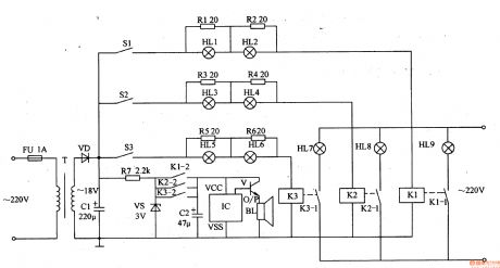
The circuit consists of power circuit, triggers control circuit and the acousto-optic call circuit. (It is showed in picture 9-88.)
Power circuit consists of fuse FU, power transformer T, rectifier diode VD, filter capacitor Cl, limiting resistor R7 and zener diode VS.
Triggers control circuit consists of Sl-S3 (ward bedside switch), resistors Rl-R6 and light HLl-H calendar and relay Kl-K3.
The acousto-optic call circuit consists of light HU-HLg, KI-K3 normally open contact, capacitor C2, music integrated circuit IC, transistor V, and the speaker BL.
This ward caller consists of power supply circuit ,trigger-control circuit and acousto-optic calling circuit.
When S1-S3 are not pressed, HL1-HL9 are all off and BL is noiseless. When one of S1-S3 is pressed, the relay in this branch closes, and the indicator is on. At the same time IC is power on and the music electrical signal output by O/P is amplified by V to drive BL to send out music sound. For example while S2 is pressed, HL3 and HL4 is on. Then K2 closes, and the normally open contacts K2-1 and K2-2 are switched on to make HL8A on, and BL sends out music sound.
Reprinted Url Of This Article:
http://www.seekic.com/circuit_diagram/Signal_Processing/Ward_Caller_Five.html
Print this Page | Comments | Reading(3)

Article Categories
power supply circuit
Amplifier Circuit
Basic Circuit
LED and Light Circuit
Sensor Circuit
Signal Processing
Electrical Equipment Circuit
Control Circuit
Remote Control Circuit
A/D-D/A Converter Circuit
Audio Circuit
Measuring and Test Circuit
Communication Circuit
Computer-Related Circuit
555 Circuit
Automotive Circuit
Repairing Circuit
Code: