Sensor Circuit
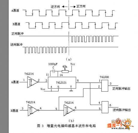
Incremental Photoelectric Encoder Basic Waveforms and Circuit
Published:2011/5/17 2:38:00 Author:Sharon | Keyword: Incremental, Photoelectric Encoder, Basic Waveforms | From:SeekIC

Incremental encoder is a sensor output pulse. Its encoder disk and resolution is much simpler and higher than those of the absolute encoder. Usually it only requires three code channels, where the code channels actually do not have the absolute meaning of the encoder code channel, but form the count pulse.Its encode disk external and middle channel have the same number of average-distributed transparent or no-transparent fan-shaped area (raster), and the two fan-shaped areas are separated by half-area. When the decode disc rotates, the output signal is pulse signal with 90 °phase shift of the A phase and B phase. And pulse signal has only a light slit produced by the third code channel (It acts as a basis of encoder disk and provides an initial zero signal for count).
The phase relationship of A and B two output signals (lead or lag) can determine the direction of rotation. Figure 3 (a) shows when the encoder disk rotates forward, A channel's pulse waveform is advanced than that of B channel by π / 2, while in reversal, A channel's pulse waveform legs behind that of B channel by π / 2. Figure 3 (b) is a real circuit, with the bottom of A channel's shaping wave triggering the monostable and generating positive pulse, and then touching with B channel's shaping wave. When the encoder disk rotates forward, only positive pulse outputs, otherwise, only the reverse pulse outputs.
Reprinted Url Of This Article:
http://www.seekic.com/circuit_diagram/Sensor_Circuit/Incremental_Photoelectric_Encoder_Basic_Waveforms_and_Circuit.html
Print this Page | Comments | Reading(3)

Article Categories
power supply circuit
Amplifier Circuit
Basic Circuit
LED and Light Circuit
Sensor Circuit
Signal Processing
Electrical Equipment Circuit
Control Circuit
Remote Control Circuit
A/D-D/A Converter Circuit
Audio Circuit
Measuring and Test Circuit
Communication Circuit
Computer-Related Circuit
555 Circuit
Automotive Circuit
Repairing Circuit
Code: