
Circuit Diagram
Index 527
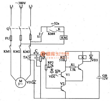
The auto time delay step-down starting regulated power supply circuit
Published:2011/8/23 22:37:00 Author:qqtang | Keyword: time delay, regulated power supply

The principle of the circuit is shown in the figure. When the switch S1 is pulled in, the current is phase-shifted by the load and the net composed of R5, R2 and C1, the circuit is conducted by the dual-channel trigger diode VD3 and trigger SCR. As the resistance of R2 is high, the SCR conducting angle is small. At the moment, the output terminal can get a low voltage(which can be designed to be 0 as the delaying starter). SCR can be chosen as 6A/600V, the trigger current is lower than 10mA SCR; VT1 is an ordinary MOSFET, such as 3DJ6 or 3DJ7,etc. (View)
View full Circuit Diagram | Comments | Reading(1007)
TXD1742--The fully automated AC stabilizer of continuous adjustment
Published:2011/8/23 22:37:00 Author:qqtang | Keyword: AC stabilizer, continuous adjustment

The stabilizer is a servo system controlled auto stabilizer. Its characterizes continuous adjusted stabilization course, ±1.5% stabilizing precision, the 165~250V power supply adapting range, the over-voltage protection and auto reset function. The circuit is shown in the figure, which mainly consists of 3 parts, i.e the self-coupled transformer and servo motor; regulated comparator adjustment and over-voltage protection circuit; DC power supply circuit. (View)
View full Circuit Diagram | Comments | Reading(6708)
The Anchuan 616G5 frequency converter typical connection circuit
Published:2011/8/12 10:46:00 Author:qqtang | Keyword: frequency converter, typical connection circuit

View full Circuit Diagram | Comments | Reading(737)
The motor protector circuit
Published:2011/8/23 22:38:00 Author:qqtang | Keyword: motor protector

The working principle of the device is shown in figure 21. LSE component is stringed in A, B and C. When the 3-phase wire is intact, 4-pin of LSE is outputting a high LEV, meanwhile the relays of J1, J2 and J3 are in the closed state, so the 3-phase AC contcator CJ is pulled in, and the contactors of CJ1, CJ2 and CJ3 are self-protecting, the motor is working normally. If one of A, B, C 3-phase power supplies is broken down, then the part between 1-pin and 2-pin of one of the LSEs will be broken down. (View)
View full Circuit Diagram | Comments | Reading(564)
The motor phase loss protector circuit
Published:2011/8/23 22:38:00 Author:qqtang | Keyword: motor, phase loss, protector
Here is to introduce a motor phase loss protector circuit, which characterizes simple circuit, low cost, easy production, stable and reliable working, no debugging and so on, it is suitable for phase loss over-current protection of intermediate and micro 3-phase motors. The working principles The motor phase loss protector consists of the current inter-inductor TAl-TA3, heat relay KR, rectifier diode VD1-VD14, relay K1-K3, starting key S1, stop key S2 and AC contactor KM,etc, see as figure 4-120.
(View)
View full Circuit Diagram | Comments | Reading(1520)
The 3-phase asynchronous motor connection circuit
Published:2011/8/23 22:38:00 Author:qqtang | Keyword: 3-phase, asynchronous motor

The 3-phase asynchronous motor connection circuit: each of the 3 three stator coils of the motor has 2 outgoing lines. One of them is called the head end, the other is the tail end. The head end is regulated to be represented by D1, the tail end is represented with D4; the second coil head end is represented with D2, the tail end is represented with D5; the head and tail ends of the third coil are represented with D3 and D6 respectively. The 6 outgoing lines are connected with the terminals of the box, and there are the marks of D1~D6 on the wiring terminals.
(View)
View full Circuit Diagram | Comments | Reading(1814)
The draft fan circuit (2)
Published:2011/8/23 22:38:00 Author:qqtang | Keyword: draft fan

The circuit makes sure that there is enough time when Y-△ decompression is started, i.e in the KM2 coil control circuit, the 2 couples of serial contactors make sure there is enough time when Y-△ decompression is started. (View)
View full Circuit Diagram | Comments | Reading(520)
The SPT1141/1151 multi-functional switch controller application circuit
Published:2011/8/13 1:31:00 Author:qqtang | Keyword: multi-functional switch controller, application circuit

View full Circuit Diagram | Comments | Reading(558)
The YDS100/200 switch power supply integrated circuit
Published:2011/8/13 1:33:00 Author:qqtang | Keyword: switch power supply, integrated circuit

View full Circuit Diagram | Comments | Reading(618)
The digital thermometer circuit composed of highly precise micro medical digital clinical thermometer HT7500
Published:2011/8/13 1:43:00 Author:qqtang | Keyword: digital thermometer, digital clinical thermometer


View full Circuit Diagram | Comments | Reading(1898)
The MAX639 multi-functional switch integrated stabilizer
Published:2011/8/23 22:36:00 Author:qqtang | Keyword: multi-functional switch, integrated stabilizer


The solid/adjustable output multi-functional switch stabilizing integrated circuit is a high-efficient and multi-functional switch stabilizer circuit, whose output voltage is +5V, input voltage is 6.5~11.5V, output current is 100mA. Its efficiency is high, and it is fixed with the e-switch control terminal and battery low voltage test terminal which are controlled by the logic LEV, it characterizes low consumption, low voltage difference and strong functions,etc. The circuit is used in portable devices and instruments, etc, whose basic usage is shown in the figure.
(View)
View full Circuit Diagram | Comments | Reading(825)
The application circuit of the MAX667 multi-functional linear integrated stabilizer (3)
Published:2011/8/13 1:45:00 Author:qqtang | Keyword: application circuit, multi-functional, linear integrated stabilizer

View full Circuit Diagram | Comments | Reading(719)
The application circuit of the MAX667 multi-functional linear integrated stabilizer (2)
Published:2011/8/13 1:47:00 Author:qqtang | Keyword: application circuit, multi-functional, linear integrated stabilizer

View full Circuit Diagram | Comments | Reading(633)
The application circuit of the MAX667 multi-functional linear integrated stabilizer (1)
Published:2011/8/13 1:48:00 Author:qqtang | Keyword: application circuit, multi-functional, linear integrated stabilizer

View full Circuit Diagram | Comments | Reading(716)
The backward converter of MC34063 application circuit
Published:2011/8/13 1:51:00 Author:qqtang | Keyword: backward converter, application circuit

View full Circuit Diagram | Comments | Reading(2815)
The step-down converter (large current) of MC34063 application circuit
Published:2011/8/13 1:57:00 Author:qqtang | Keyword: step-down converter, large current, application circuit

View full Circuit Diagram | Comments | Reading(5096)
The booster converter (large current) of MC34063 application circuit
Published:2011/8/13 1:59:00 Author:qqtang | Keyword: booster converter, large current, application circuit

View full Circuit Diagram | Comments | Reading(3023)
The step-down converter of MC34063 application circuit
Published:2011/8/13 2:01:00 Author:qqtang | Keyword: step-down converter, application circuit

View full Circuit Diagram | Comments | Reading(3128)
The booster converter of MC34063 application circuit
Published:2011/8/13 2:02:00 Author:qqtang | Keyword: booster converter, application circuit

View full Circuit Diagram | Comments | Reading(6190)
The wide range digital capacitor gauge(NE555, CD4017 and MC14553B)
Published:2011/8/14 22:07:00 Author:qqtang | Keyword: wide range, digital capacitor gauge


In the figure is a wide range digital capacitor gauge(NE555, CD4017 and MC14553B). The gauge consist of the pulse generator, reference capacitor volume-frequency converter, capacitance volume-frequency converter under test, counting controller, counter and display circuit, etc. The pulse generator is a multi-resonance oscillator which consists of the IC1, R1, R2 and C1(R3, R4 and C2), its oscillating is f1= 1.44/(R1+2R2)C1, or f2=1.44/(R3+2R4)C2. The upper edge of the pulse output by 9-pin makes the D trigger IC2 (CD4013) output terminal Q generate a low LEV.
(View)
View full Circuit Diagram | Comments | Reading(1793)
| Pages:527/2234 At 20521522523524525526527528529530531532533534535536537538539540Under 20 |
Circuit Categories
power supply circuit
Amplifier Circuit
Basic Circuit
LED and Light Circuit
Sensor Circuit
Signal Processing
Electrical Equipment Circuit
Control Circuit
Remote Control Circuit
A/D-D/A Converter Circuit
Audio Circuit
Measuring and Test Circuit
Communication Circuit
Computer-Related Circuit
555 Circuit
Automotive Circuit
Repairing Circuit