
Circuit Diagram
Index 523
Infrared remote control fan speed control switch (555, LM324, CD4017)
Published:2011/8/25 20:49:00 Author:TaoXi | Keyword: Infrared, remote control, fan speed, control switch

The infrared remote control fan speed control switch is as shown in the figure. This circuit is composed of the infrared transmitter, the infrared receiver, the decoder. The infrared transmitter includes the low-frequency multivibrator which is composed of the IC1 and D1, R1, R2, C2 and the multivibrator which is composed of the IC2 and R3, R4, C4, C5, W1. The oscillation cycle of IC1 is T=tcharging + tdischarging, the tcharging=0.693R2C2, it is about 400μs; tdischarging=0.693R1C2, it is about 15ms, the output waveform duty cycle is about 3%. IC2 is corresponding to two kinds of oscillation frequencies: f1=1.44/(R3+2R4+2Rw1)(C4),f2=1.44/(R3+2R4+2Rw1)(C4+C5), in the figure, the f=20kHz, f2=10kHz.
(View)
View full Circuit Diagram | Comments | Reading(3798)
The switch power supply of STR5412
Published:2011/8/13 2:25:00 Author:qqtang | Keyword: switch power supply

View full Circuit Diagram | Comments | Reading(2254)
The visible laser Nc modulation drive
Published:2011/8/13 2:27:00 Author:qqtang | Keyword: visible, laser Nc, modulation drive

View full Circuit Diagram | Comments | Reading(593)
Constant amplitude sawtooth wave generating circuit composed of the μA741
Published:2011/8/25 20:59:00 Author:TaoXi | Keyword: Constant amplitude, sawtooth wave, generating circuit
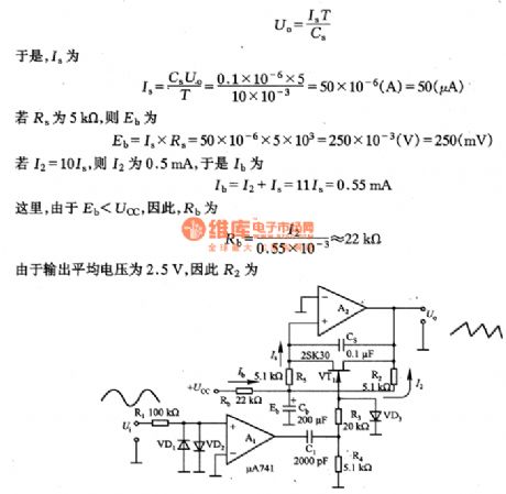
The constant amplitude sawtooth wave generating circuit composed of the μA741 is as shown in the figure. This circuit changes the input signal of the external oscillator into the square wave signal, and this signal changes into the pulse signal that can drive the VT1 grid electrode through RC(R4, C1) differential, the VT1 makes the integral capacitance Cs in the short-circuit state periodically, A2 outputs the constant amplitude sawtooth wave with the cycle of T.
Now I briefly explain the method of setting circuit parameters. If the frequency of the external input oscillation signal is 50HZ (the corresponding period T is lOms), the VT1 conduction resistor is 2OOΩ.
(View)
View full Circuit Diagram | Comments | Reading(1340)
The moving direction sensor (CD4011) composed of gate circuits
Published:2011/8/13 2:33:00 Author:qqtang | Keyword: moving direction sensor, gate circuits
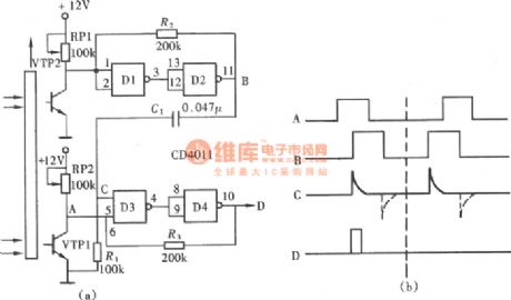
The moving direction sensor is a necessary element in counters on the manufacturing auto line. In the figure is the moving direction sensor composed of gate circuits (CD4011), but the sensor is only used to recognize the forward direction, not the backward direction, it is a single moving direction sensor. (View)
View full Circuit Diagram | Comments | Reading(1945)
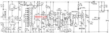
Infrared automatic faucet controller (555, LM567, SP110)
Published:2011/8/25 21:08:00 Author:TaoXi | Keyword: Infrared, automatic, faucet, controller

The infrared automatic faucet controller is as shown in the figure. This control circuit has the transmitter circuit and the receiver decoding control circuit. The transmitter circuit is composed of the multivibrator and the infrared emitting diode, the receiving circuit is composed of the infrared receiving tubes D1 and D2, the operational amplifier IC2(CA741), the audio decoder IC3 (LM567), the AC solid-state relay IC4(SP110), the power supply circuit. In the transmitter circuit, the multivibrator is composed of the IC1 (555) and R1, R2, C1, the oscillation frequency f=1.44/(R1+2R2)C1, in this figure, the corresponding frequency is about 40kHz.
(View)
View full Circuit Diagram | Comments | Reading(3000)
Electric fan multi-function remote control circuit
Published:2011/8/25 21:10:00 Author:TaoXi | Keyword: Electric fan, multi-function, remote control

Transmitter:
Receiver:
(View)
View full Circuit Diagram | Comments | Reading(1554)
Ceiling fan infrared remote control circuit (2)
Published:2011/8/25 21:13:00 Author:TaoXi | Keyword: Ceiling fan, infrared, remote control

Ceiling fan infrared remote control circuit (2)
(View)
View full Circuit Diagram | Comments | Reading(4573)
NFB type tone control circuit
Published:2011/8/25 21:16:00 Author:TaoXi | Keyword: NFB type, tone control

The NFB type tone control circuit is as shown in the figure. This kind of circuit has low output impedance and high input impedance, so it has the good S/N and low distortion characteristics. The control potentiometer need to use the C type potentiometer.
(View)
View full Circuit Diagram | Comments | Reading(1672)
The connector circuit with 3-line serial spot intelligent temperature sensor DS1620 and SP1 general line
Published:2011/8/13 2:37:00 Author:qqtang | Keyword: connector circuit, serial spot, temperature sensor

View full Circuit Diagram | Comments | Reading(755)
The high precision and impedance device amplifier composed of OPA2111
Published:2011/8/13 2:55:00 Author:qqtang | Keyword: high precision, device amplifier

In the figure is the high precision and impedance device amplifier composed of OPA2111. The voltage of the figured circuit can be magnified to Av=10*(1+2R2/R1)=1000. The rear stage is fixed with a difference amplifier circuit whose gain is 10 times, which can expand the input common mode voltage range to ±10V. (View)
View full Circuit Diagram | Comments | Reading(784)
Ceiling fan infrared remote control circuit (1)
Published:2011/8/25 21:12:00 Author:TaoXi | Keyword: Ceiling fan, infrared, remote control

The Ceiling fan infrared remote control circuit (1)
(View)
View full Circuit Diagram | Comments | Reading(5410)
RC type tone control circuit
Published:2011/8/25 21:23:00 Author:TaoXi | Keyword: RC type, tone control

The RC type tone control circuit is as shown in the figure. The tone control circuits are divided into the RC type, the input series voltage feedback NFB type, the input parallel voltage feedback BAX type. The RC type tone control circuit which is as shown in figure 2-42 is composed of the low-pass filter and high-pass filter (composed of the capacitor and resistor), the filter characteristics is controlled by the potentiometer. This kind of circuit has the low input impedance and higher output consumption, so you need to connected the buffer amplifier with it. The rated consumption of the filter is about 15-20dB, so the input buffer need to have the wide dynamic range.
(View)
View full Circuit Diagram | Comments | Reading(1306)
The equipment amplifier with the function of expanding common mode range
Published:2011/8/23 22:40:00 Author:qqtang | Keyword: equipment amplifier, common mode range

In the figure is the equipment amplifier with the function of expanding common mode range. In the circuit, A1, A2 and A4 are composed of the high-precision equipment amplifier INA10 or INA102. Seeing from the figure, the magnifying multiple of A1, A2 and A3 is 100, the rear stage amplifier is a high-precision unit gain amplifier INA105, the connection method of the amplifier is non-inverting input and follower output, i.e the 4 resistors in the circuit are in parallel connection respectively. In figure (b) is the internal structure of INA101. (View)
View full Circuit Diagram | Comments | Reading(762)
Multi-functional remote control circuit (555, LM909)
Published:2011/8/26 0:56:00 Author:TaoXi | Keyword: Multi-functional, remote control

The multi-functional remote control circuit is as shown in the figure, this circuit is composed of the generator and receiver. The transmitter is composed of the astable multivibrator, the audio-frequency generator and the RF oscillator. The receiver uses the LM909. The multivibrator is composed of the IC1 (555) and R1, R2, R3, C3, you can change the charging and discharging time constant by using the switch K1. When K1 is in the position 1 , the duty cycle D=(R2+R3)/(R1+R2+R3+R4)≈60%; when K1 is in the position 2 , the duty cycle D=(R2+R3)/(R1+R2+R3+R4)≈30%; When K1 is in the position 3 , the duty cycle D=(R2+R3)/(R1+R2+R3+R4)≈100%(pin-3 of IC1 outputs the low level signal).
(View)
View full Circuit Diagram | Comments | Reading(2097)
The single main power low consumption device amplifier composed of INA102
Published:2011/8/13 3:00:00 Author:qqtang | Keyword: single main power, low consumption, device amplifier

View full Circuit Diagram | Comments | Reading(705)
Electric fan infrared remote control circuit (Greatwall FS-19-40)
Published:2011/8/25 21:24:00 Author:TaoXi | Keyword: Electric fan, infrared, remote control, Greatwall

The Electric fan infrared remote control circuit (Greatwall FS-19-40) is as shown in the figure.
(View)
View full Circuit Diagram | Comments | Reading(1608)
Power control circuit with the thyristor
Published:2011/8/25 21:28:00 Author:TaoXi | Keyword: Power control circuit, thyristor

The power control circuit with the thyristor is as shown in the figure, the circuit uses the L1, C1, C2 and R2 to form the filter circuit, and it can be used to filter the power supply noise. The rectifier and voltage regulator circuit is composed of the VDl, VD2 and VD3, it can supply the operating voltage for the control circuit. The trigger circuit of the thyristor VS is composed of the VT1 and the surrounding components. The thyristor VS controls the voltage of the load.
(View)
View full Circuit Diagram | Comments | Reading(1723)
The micro heater temperature control circuit composed of 3-line connector intelligent temperature sensor DS1620
Published:2011/8/13 3:05:00 Author:qqtang | Keyword: micro heater, temperature control, temperature sensor

The micro heater temperature control circuit composed of 3-line serial spotconnector intelligent temperature sensor DS1620 is shown in the figure. (View)
View full Circuit Diagram | Comments | Reading(1685)
Burst sound generator circuit composed of the SN7473
Published:2011/8/25 21:47:00 Author:TaoXi | Keyword: Burst sound, generator circuit
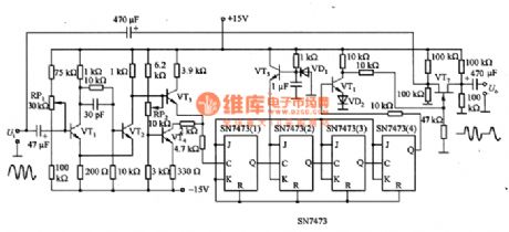
The burst sound generator circuit composed of the SN7473 is as shown in the figure. When the sine wave is changing into the burst sonic, it needs the wveform shaping circuit, the frequency dividing circuit and the switching circuit. As the figure 6-64 shows, the waveform shaping circuit uses the schmitt circuit; the frequency dividing circuit uses the T trigger; the switching circuit uses the FET tube. The SN7473 is the frequency dividing circuit, when the Q outputs the high level, the VT6 conducts, the grid electrode of VT7 outputs the low level and cuts off to change into the high impedance and output the U. When the Q outputs the low level, the VT6 cuts off, the VT7 conducts to output the U.
(View)
View full Circuit Diagram | Comments | Reading(1455)
| Pages:523/2234 At 20521522523524525526527528529530531532533534535536537538539540Under 20 |
Circuit Categories
power supply circuit
Amplifier Circuit
Basic Circuit
LED and Light Circuit
Sensor Circuit
Signal Processing
Electrical Equipment Circuit
Control Circuit
Remote Control Circuit
A/D-D/A Converter Circuit
Audio Circuit
Measuring and Test Circuit
Communication Circuit
Computer-Related Circuit
555 Circuit
Automotive Circuit
Repairing Circuit