LED and Light Circuit
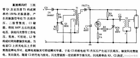
DC strobe light circuit diagram
Published:2011/9/7 2:16:00 Author:Lucas | Keyword: DC strobe light | From:SeekIC

Transistor Q1 and transformer T1 form the oscillator with frequency about 15kHz, and the oscillation signal is boosted by the T1 secondary, rectified by diode, storaged by C1 to be about 300V DC voltage. Neon bulb, SCR, L2, etc. constitute a time interval trigger circuit. When the charging voltage on the capacitor C2 is up to the neon bulb starter voltage, starter current will trigger SCR to get transient conduction, so the discharge of C2 can get ten thousand volts after boosting by T2, then it will trigger the flashing tube to discharge and emit strong light. With the charge and discharge of the C2, the flashing tube will flash at a certain frequency rhythm.
Reprinted Url Of This Article:
http://www.seekic.com/circuit_diagram/LED_and_Light_Circuit/DC_strobe_light_circuit_diagram.html
Print this Page | Comments | Reading(3)

Article Categories
power supply circuit
Amplifier Circuit
Basic Circuit
LED and Light Circuit
Sensor Circuit
Signal Processing
Electrical Equipment Circuit
Control Circuit
Remote Control Circuit
A/D-D/A Converter Circuit
Audio Circuit
Measuring and Test Circuit
Communication Circuit
Computer-Related Circuit
555 Circuit
Automotive Circuit
Repairing Circuit
Code: