Signal Processing
Broadband pulse generator circuit diagram with independent adjustable duty cycle
Published:2011/9/14 9:14:00 Author:nelly | Keyword: Broadband pulse generator, adjustable duty cycle | From:SeekIC
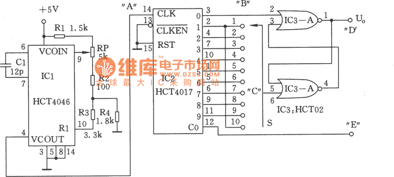
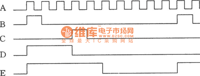
As shown in the figure, this circuit can provide adjustable square wave and rectangular wave generator 1.2KHz~2.7KHz work frequency, 10~90% duty cycle. The frequency comes form the voltage controlled oscillator and correlative components. The 1.2KHz~2.7KHz oscillation frequency is adjusted by potentiometer RP. The counter IC2 provides set pulse which form Q0 output to SR trigger IC3, the corresponding reset pulse is decided by Q1~Q9 output select switch S. The output frequency is 1/10 of IC2's input, the square wave is obtained form carry output C .
Reprinted Url Of This Article:
http://www.seekic.com/circuit_diagram/Signal_Processing/Broadband_pulse_generator_circuit_diagram_with_independent_adjustable_duty_cycle.html
Print this Page | Comments | Reading(3)

Article Categories
power supply circuit
Amplifier Circuit
Basic Circuit
LED and Light Circuit
Sensor Circuit
Signal Processing
Electrical Equipment Circuit
Control Circuit
Remote Control Circuit
A/D-D/A Converter Circuit
Audio Circuit
Measuring and Test Circuit
Communication Circuit
Computer-Related Circuit
555 Circuit
Automotive Circuit
Repairing Circuit
Code: