555 Circuit
555 Water level-controlled Circuit
Published:2011/9/3 10:40:00 Author:Zoey | Keyword: Water level-controlled | From:SeekIC


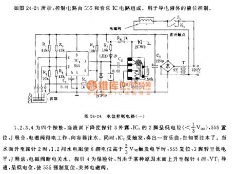
As shown in the picture 24-24, the controlling circuit is composed of 555 and a music IC circuit. This circuit is used to control the conductive liquid.
1,2,3, and 4 refer to four pins. When the liquid level goes down and Pin 3 is exposed, Pin 2 of IC1will bein low level(<1/3VDD), 555 will set and J will close, and solenoid valve will get electrical power and begin to work and infuse water to the container. Meanwhile, IC2 will be triggered and play music to inform people to infuse water. When water levelreachespin 2, water resistance between pin 1 and pin 2 will make the level of pin 6 higher than 2/3VDD, then 555 will reset, pin 3 will be in low level, J willrelease, and solenoid valve will cut off electric power and water supply. Pin 4 is an insurance needle, when water level reaches pin 4, VT1 will conduct and be in low level, forcing 555 to reset and cut off the solenoid valve.
Reprinted Url Of This Article:
http://www.seekic.com/circuit_diagram/555_Circuit/555_Water_level_controlled_Circuit.html
Print this Page | Comments | Reading(3)

Article Categories
power supply circuit
Amplifier Circuit
Basic Circuit
LED and Light Circuit
Sensor Circuit
Signal Processing
Electrical Equipment Circuit
Control Circuit
Remote Control Circuit
A/D-D/A Converter Circuit
Audio Circuit
Measuring and Test Circuit
Communication Circuit
Computer-Related Circuit
555 Circuit
Automotive Circuit
Repairing Circuit
Code: