Basic Circuit
Temperature compensation circuit with the thermistor
Published:2011/8/24 21:30:00 Author:Christina | Keyword: Temperature, compensation, thermistor | From:SeekIC

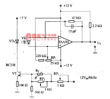
The temperature compensation circuit with the thermistor is as shown in the figure. It is designed as the temperature-compensation circuit of the infrared light-emitting diode VD1, the VD1 can be used as the photodetector of the modulated light, the maximum current is 50mA, the temperature range is 10-55℃. RT can be used as the thermistor with the negative temperature coefficient, and it is connected with the base of VT1 to reduce the self-heating effect of the thermistor. The RP2 and RP3 can be used to adjust the temperature compensation feature. VD2 is the receiver that can amplify the receiving signal through the TAA761.
Reprinted Url Of This Article:
http://www.seekic.com/circuit_diagram/Basic_Circuit/Temperature_compensation_circuit_with_the_thermistor.html
Print this Page | Comments | Reading(3)

Article Categories
power supply circuit
Amplifier Circuit
Basic Circuit
LED and Light Circuit
Sensor Circuit
Signal Processing
Electrical Equipment Circuit
Control Circuit
Remote Control Circuit
A/D-D/A Converter Circuit
Audio Circuit
Measuring and Test Circuit
Communication Circuit
Computer-Related Circuit
555 Circuit
Automotive Circuit
Repairing Circuit
Code: