Basic Circuit
The FM circuit with the transfiguration diode
Published:2011/8/24 21:34:00 Author:Christina | Keyword: FM, transfiguration diode | From:SeekIC

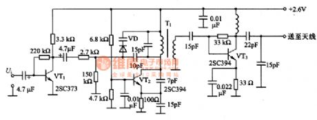
The FM circuit with the transfiguration diode is as shown in the figure. In this circuit, the VT1 changes the signal Ui which is produced by the electret condenser microphone into the operating voltage of the varactor diode VD. The LC oscillator circuit which is composed of the VT2 produces the 80MHz band signal. We can use the varactor diode VD to change the frequency of the resonant circuit, so we do the frequency modulation directly. When the output Vi is 3mV, the modulation frequency is +/-25khz. The VT3 is the high-frequency amplifier, it amplifies the modulated signal to 2.3mV and delivers it to the antenna.
Reprinted Url Of This Article:
http://www.seekic.com/circuit_diagram/Basic_Circuit/The_FM_circuit_with_the_transfiguration_diode.html
Print this Page | Comments | Reading(3)

Article Categories
power supply circuit
Amplifier Circuit
Basic Circuit
LED and Light Circuit
Sensor Circuit
Signal Processing
Electrical Equipment Circuit
Control Circuit
Remote Control Circuit
A/D-D/A Converter Circuit
Audio Circuit
Measuring and Test Circuit
Communication Circuit
Computer-Related Circuit
555 Circuit
Automotive Circuit
Repairing Circuit
Code: