
Circuit Diagram
Index 1664
ASK/FM 433/315 MHz Emitter Circuit Diagram
Published:2011/6/19 7:29:00 Author:Vicky | Keyword: ASK/FM 433/315 MHz Emitter

TH71071 applied circuit
TH71071 is a monolithic emitter chip which reaches standards of EN 300 220 and the analogs. It is available for keyless entering system, remote control/remote measuring system, data communication sysytem and security sysetem etc.
Main technical features are as follows:
·Work frequency range: 310~440 MHz;
·ASK/FM modulation mode;
·ASK is conducted by interior power amplifier/gained by closing keying
·FM which makes use of externally-linked variode
·Voltage of power supply: 2.2~5.5 V;
·Work current: 4.8~11.5 mA, maximum stand-by current: 0.1μA;
·Output power: -12~+2 dBm. (View)
View full Circuit Diagram | Comments | Reading(797)
The example circuit of the COB component
Published:2011/6/28 19:01:00 Author:TaoXi | Keyword: components, COB component
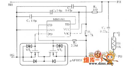
The COB(Chip On Board) component uses the circuit structure of the single lithium-ion battery protection component as the foundation, it is one kind of circuit form that encapsulates all of the components with the resin. The features of it are as shown: 1.Small volume and light weight. There is no need to install any metal wiring rack if the package has the integrated protection circuit and the naked chip FET component. 2.Water resisting property and insulating quality. Because the circuit component is sealed with the resin, so it has the water resisting property. 3. Reduces the fault in the secondary installation. The MM1491 is the single lithium-ion battery protection integrated circuit.
(View)
View full Circuit Diagram | Comments | Reading(616)
Infrared remote control 40Hz carrier wave signal generating circuit
Published:2011/6/26 5:51:00 Author:TaoXi | Keyword: Infrared remote control, 40Hz, carrier wave, signal generating circuit
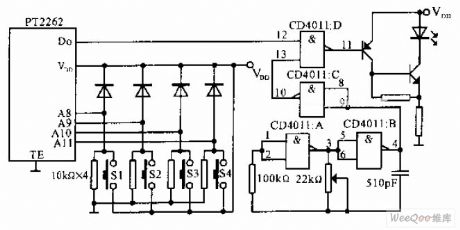
The circuit that uses the infrared remote control 40Hz carrier wave signal generating circuit as the infrared transmitter is as shown in the figure, when you press one or several buttons of the S1-S4, the PT2262 gets power to work and it outputs the pulse data flow. At the same time, the pulse oscillator which is composed of the CD4011 and CD4011B starts working, the oscillation frequency can be adjusted to 40KHz by the 22Ω potentiometer, the frequency is the infrared carrier wave frequency. The output data flow of PT2262 modulates the 40KHz carrier wave in the CD4011D, then the output data flow drives the infrared led through the transistor to output the infrared signal.
(View)
View full Circuit Diagram | Comments | Reading(1251)
FM Emitter Module Circuit Diagram
Published:2011/6/19 7:59:00 Author:Vicky | Keyword: FM Emitter Module

T5 is a micro UHF emitter module and is used with receptor module R5. It is suitable for application in one point to one point or multipoint connection, such as vehicle warning system, remote control of warehouse gate and house & commerce security system.
Main technical features are as follows:
·Work frequency: 433.92 MHz;
·Data transfer rate up to l28 Kb/s;
·Emitting distance up to 300 m;
·Voltage of power supply: 4.5~5.5 V;
·Maximum work current: l2 mA;
·Maximum RF power: +12 dBm. (View)
View full Circuit Diagram | Comments | Reading(619)
Voltage control oscillator circuit composed of the Schmitt trigger
Published:2011/6/26 3:08:00 Author:TaoXi | Keyword: Voltage control oscillator, Schmitt trigger
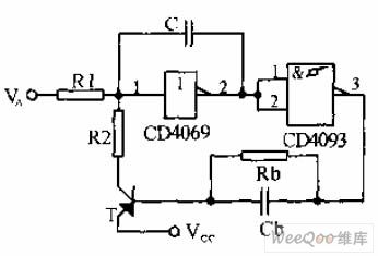
The voltage control oscillator (negative voltage control oscillator) that is composed of the Schmitt trigger is as shown in the figure, the oscillation frequency decreases with the increasing of VA, the variation range of VA is VSS-VTBC, this kind of circuit has wide adjustment range and good linear relation.
(View)
View full Circuit Diagram | Comments | Reading(670)
Capacitive closing switch circuit composed of the division devices
Published:2011/6/24 23:46:00 Author:TaoXi | Keyword: Capacitive closing switch, division devices
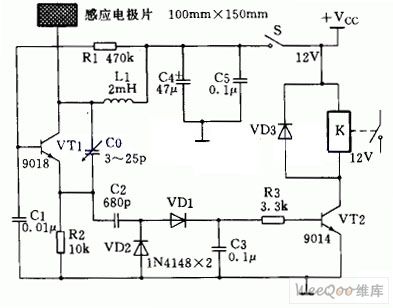
The capacitive closing switch circuit is composed of a RF oscillator circuit and a detection board. The capacitive sensing type controller principle diagram (composed of the division devices) is as shown in the figure.
In the figure, the RF oscillator circuit is composed of the transistor VT1 and the surrounding components; the metal induction electrode plate is connected with the collector of VT1 that can be used as the detector. When there is no conductor closing the induction electrode plate, the oscilation circuit which is composed of the VT1 oscillates normally, at this time the RF voltage signal which is output by the VT1 emitter is changed into the DC control signal after it is detected by VD1 and VD2, this signal conducts the switching tube VT2, the relay closes to connect the power supply of the controlled circuit.
(View)
View full Circuit Diagram | Comments | Reading(1285)
GuangZhou HONDA Fit saloon car 6-speed CVT + 7-speed mode circuit 2
Published:2011/6/19 19:08:00 Author:TaoXi | Keyword: GuangZhou, HONDA, Fit, saloon car, 6-speed, CVT, 7-speed mode
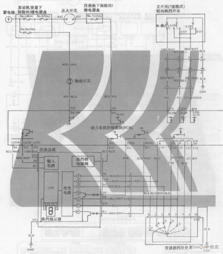
GuangZhou HONDA Fit saloon car 6-speed CVT + 7-speed mode circuit (View)
View full Circuit Diagram | Comments | Reading(390)
TTL server control circuit
Published:2011/6/19 19:13:00 Author:TaoXi | Keyword: TTL, server, control circuit
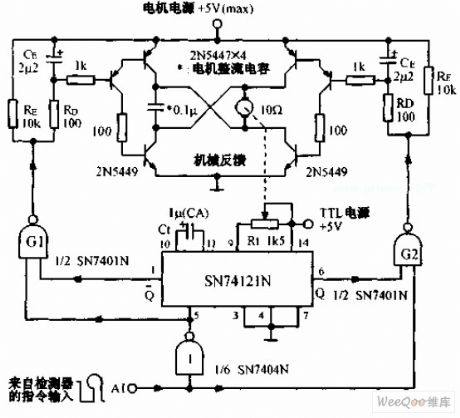
The TTL server control circuit can be used in the 9-channel control system. This system has 9 same servos, the decoder of the data transmission line (DTL) receiving port sends the signal to the servo, the command pulse controls the rotation direction and the rotation duration of the electromotor.
(View)
View full Circuit Diagram | Comments | Reading(651)
555 simple color TV additional remote control circuit
Published:2011/6/15 22:07:00 Author:TaoXi | Keyword: 555, simple, color TV, additional remote control
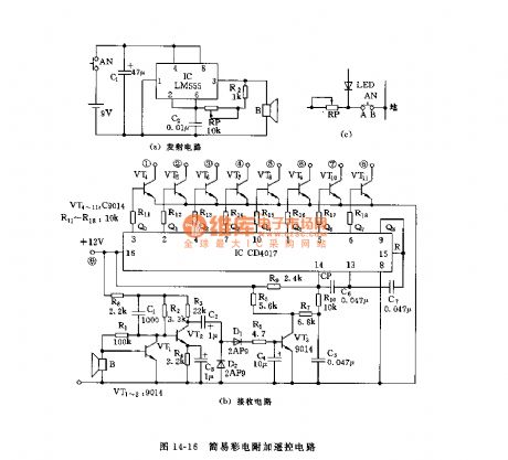
The color TV additional circuit is as shown in figure 14-16. The astable multivibrator is composed of the 555 and R2, RP, C2, the oscillation frequency is decided by the RP, R2, C2. The receiving circuit is composed of the amplifier circuit, the rectifier circuit and the counting circuit, the CD4017 is a decimal count / pulse distributor integrated circuit. When the CD4017 receives the control signal, the Q0~Q7 successively outputs the high level to control the conduction and cut-off of the VT4~VT11 transistors, and it also controls the on-off of the color TV's primary switch. In figure (b), the collector electrodes of VT4~VT11 are connected with the 1-8 connection points of the manual control preliminary selection button, such as the point A of figure (c).
(View)
View full Circuit Diagram | Comments | Reading(1216)
Radio Frequency Modulator Circuit Diagram
Published:2011/6/19 9:11:00 Author:Vicky | Keyword: Radio Frequency Modulator

The above picture is the detailed circuit of radio frequency modulator. IC1 is integrated circuit TA7673 especially for modulator, the pins 10 & 11 of which produce picture carrier signal by externally connection to crystal oscillator, and pins 4 & 5 of which produce 6.5MHz secondary audio signal. Audio signal is input via pin 6 of ICl, and video signal is input via pin 16 of ICl. When crystal oscillators of different work frequency are connected to part between pin 10 and pin 11 , the circuit can then give out picture carrier signal from channel 1 to 5 in pin 2 and pin 15. The circuit doesn’t need debugging after finishing assembly, but the whole circuit uses small metal-box as shield. (View)
View full Circuit Diagram | Comments | Reading(1559)
GuangZhou HONDA Fit saloon car 6-speed CVT + 7-speed mode circuit 1
Published:2011/6/19 19:07:00 Author:TaoXi | Keyword: GuangZhou, HONDA, Fit, saloon car, 6-speed, CVT, 7-speed mode
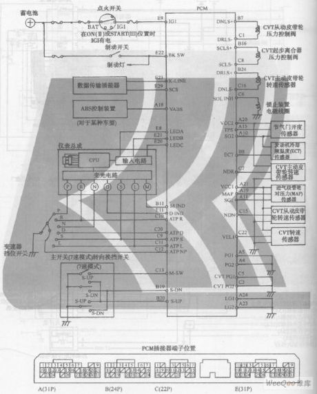
GuangZhou HONDA Fit saloon car 6-speed CVT + 7-speed mode circuit (View)
View full Circuit Diagram | Comments | Reading(449)
555 intermittent single tone audio circuit
Published:2011/6/15 21:25:00 Author:TaoXi | Keyword: 555, intermittent single tone, audio
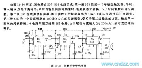
As the figure 14-30 shows, this circuit is composed of three 555 circuits, the first stage of 555 forms a monostable trigger. In peacetime, the input port A has the high electrical level, only when the negative pulse arrives, the circuit state will change. The RC time constant can be adjusted by itself. The second stage of 555 forms the multivibrator, the oscillation frequency of the figure parameter is 1Hz~10Hz, you can change it by adjusting RP2. The third stage of 555 is the multivibrator with the oscillation frequency of 1000Hz, it is controlled by the square wave. This circuit uses the double time base 555 circuit, because the drive current is large (about 200mA), so the current can drive the speaker directly.
(View)
View full Circuit Diagram | Comments | Reading(489)
555 simple TV channels transformation remote controller circuit
Published:2011/6/15 20:54:00 Author:TaoXi | Keyword: 555, simple, TV channels, transformation, remote controller
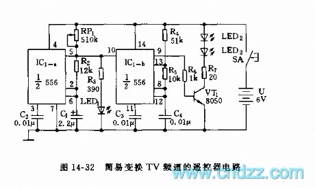
This remote control circuit uses the dual time base circuit 556 as the core, the circuit is as shown in figure 14-32.
In this figure, the astable multivibrator is composed of the IC1-a (1/2 NE556) and R2, RP1, C1, the oscillation frequency f1=1.4/(RP1+2R2)C1, you can make the resonance frequency to 1Hz by adjusting RP1. The output of it supplies the trigger pulse to the IC1-b(1/2NE556) time base circuit. The audio oscillator is composed of the IC1-b and R4, R5, C4. When there is the high level pulse, the audio oscillator starts working, the oscillation frequency f2=1.44/(R4+2R5)C4, the oscillation frequency of the figure parameters is about 2kHz. The pulse sequence is drived by VT1 to make the infrared launch tube LED to send out the 2kHz infrared modulation light.
(View)
View full Circuit Diagram | Comments | Reading(664)
555 simple electronic keyboard circuit (2)
Published:2011/6/15 19:24:00 Author:TaoXi | Keyword: 555, simple, electronic keyboard

As the figure 14-41 shows, the multivibrator is composed of the 555 and some capacitance resistance components, the oscillation frequency depends on the values of Ra, R16 and C3. f=1.44/(Ra+2R16)C3, the Ra of the formula corresponds to the different values of R1-R15, this depends on the situation of the keys K1-K15. When you are debugging the notes, you can use a 100kΩ potentiometer to debug repeatedly, and confirm every note's corresponding resistance. This circuit uses the bipolar type 555, this 555 can drive the speaker directly.
(View)
View full Circuit Diagram | Comments | Reading(1444)
555 simple electronic keyboard circuit
Published:2011/6/15 19:12:00 Author:TaoXi | Keyword: 555, simple, electronic keyboard

As the figure 14-40 shows, the controllable multivibrator is composed of the 555 and RA, RP1, C1, the oscillation frequency is related with the control voltage (pin-5), but the voltage of pin-5 depends on the partial voltage of R1~Rn and RB, and it is related with the conduction situation of VT1. The VT1 works in the amplifier region, voltage of electrode c is in the range of 3-6V, the control port pin-5 has a corresponding voltage value and it outputs the frequency of one scale or half scale. The lower the control voltage is, the higher the frequency is, but the control voltage is not less than 0.7V. When debugging, you need to adjust it repeatedly to distinguish the scales and notes. Any one of the resistors R1 ~ Rn can get the suitable resistance by using the series or parallel methods.
(View)
View full Circuit Diagram | Comments | Reading(2553)
Computer Mainboard Circuit 440GX_34
Published:2011/6/26 20:23:00 Author:zj | Keyword: Computer Mainboard, 440GX_34
View full Circuit Diagram | Comments | Reading(472)
Computer Mainboard Circuit 440GX_28
Published:2011/6/26 20:38:00 Author:zj | Keyword: Computer Mainboard, 440GX_28
View full Circuit Diagram | Comments | Reading(506)
SWF2 Type Temperature Sensor Circuit
Published:2011/6/28 7:17:00 Author:Robert | Keyword: Temperature, Sensor

The picture shows the SWF2 type temperature sensor circuit. (View)
View full Circuit Diagram | Comments | Reading(884)
M58659P Memory Integrated Circuit
Published:2011/6/28 7:28:00 Author:Robert | Keyword: Memory, Integrated


The M58659P is a memory IC produced by the Japanese Mitsubishi company which is widely used in TV sets, audio equipments, air conditioners, computers and other control systems.
1.Its functional features.
The M58659P IC has internal digital input/output interface circuit, memory matrix circuit and data registers circuit and so on.
2.Its pin's functions and data.
The M58659P IC uses 14-pin dual-in-line package. Its pin's functions are shown in the picture 8-36. Its working parameters are listed in table 8-35.
The picture shows the M58659P IC's pinout and pin's functions.
The table shows the M58659P IC's working parameter. (View)
View full Circuit Diagram | Comments | Reading(726)
M58658P Memory Integrated Circuit
Published:2011/6/28 7:34:00 Author:Robert | Keyword: Memory, Integrated
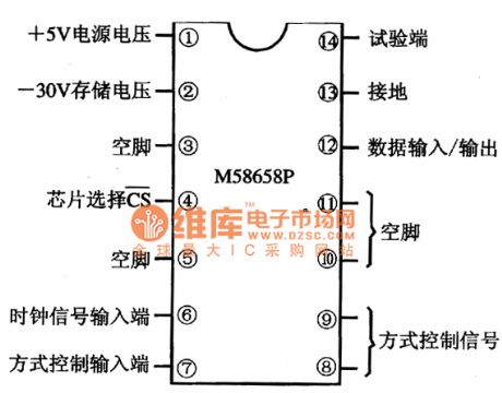

The M58658P is a memory IC produced by the Japanese Mitsubishi company which is widely used in TV sets, air conditioners,remote-control fansand other cases which needto store information.
1.Its functional features.
The M58658P IC has internal memory matrix circuit, digital input/output interface circuit, and registers circuit and so on.
2.Its pin's functions and data.
The M58658P IC uses 14-pin dual-in-line package. Its pin's functions are shown in the picture andits working parameters are listed in the table.
The picture shows the M58658P IC's pin's functions.
The table shows the M58658P IC's working parameter. (View)
View full Circuit Diagram | Comments | Reading(671)
| Pages:1664/2234 At 2016611662166316641665166616671668166916701671167216731674167516761677167816791680Under 20 |
Circuit Categories
power supply circuit
Amplifier Circuit
Basic Circuit
LED and Light Circuit
Sensor Circuit
Signal Processing
Electrical Equipment Circuit
Control Circuit
Remote Control Circuit
A/D-D/A Converter Circuit
Audio Circuit
Measuring and Test Circuit
Communication Circuit
Computer-Related Circuit
555 Circuit
Automotive Circuit
Repairing Circuit

