
Circuit Diagram
Index 1679
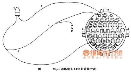
38-pin diagnosis connector reading wiring circuit
Published:2011/6/28 2:03:00 Author:Christina | Keyword: 38-pin, diagnosis connector, reading wiring circuit
View full Circuit Diagram | Comments | Reading(487)
Columnar lithium chloride humidity sensitive resistor structure circuit
Published:2011/6/28 2:20:00 Author:Christina | Keyword: Columnar, lithium chloride, humidity sensitive resistor, structure circuit
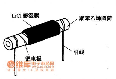
The columnar lithium chloride humidity sensitive resistor structure circuit is as shown in the figure. You can wind two parallel palladium leads on the polystyrene cylinder as the electrodes, then you can besmear the alkalization treatment lithium chloride solution on the polystyrene cylinder. Because the humidity sensing membrane can adsorb or release the water molecules to change the resistance value, so we can get the humidity value by detecting the resistance value between the electrodes.
Figure:Columnar lithium chloride humidity sensitive resistor structure circuit (View)
View full Circuit Diagram | Comments | Reading(684)
Rice cooker Circuit diagram 02
Published:2011/6/27 2:24:00 Author:zj | Keyword: Rice cooker, 01

View full Circuit Diagram | Comments | Reading(4780)
Rice cooker Circuit diagram 01
Published:2011/6/27 21:17:00 Author:zj | Keyword: Rice cooker, 01

View full Circuit Diagram | Comments | Reading(1391)
Telephone Schematic 09
Published:2011/6/27 4:11:00 Author:zj | Keyword: Telephone Schematic, 09

View full Circuit Diagram | Comments | Reading(1023)
Telephone Schematic 08
Published:2011/6/27 4:16:00 Author:zj | Keyword: Telephone Schematic, 08

View full Circuit Diagram | Comments | Reading(2416)
Telephone Schematic 07
Published:2011/6/27 4:16:00 Author:zj | Keyword: Telephone Schematic, 07

View full Circuit Diagram | Comments | Reading(950)
Telephone Schematic 06
Published:2011/6/27 4:17:00 Author:zj | Keyword: Telephone Schematic, 06

View full Circuit Diagram | Comments | Reading(631)
Telephone Schematic 05
Published:2011/6/27 4:18:00 Author:zj | Keyword: Telephone Schematic, 05

View full Circuit Diagram | Comments | Reading(724)
Telephone Schematic 04
Published:2011/6/27 4:19:00 Author:zj | Keyword: Telephone Schematic, 04

View full Circuit Diagram | Comments | Reading(1565)
Simple LED driver
Published:2011/6/28 2:15:00 Author:zj | Keyword: Simple LED driver, 9012

View full Circuit Diagram | Comments | Reading(646)
X-Y server control circuit
Published:2011/6/19 19:18:00 Author:TaoXi | Keyword: X-Y, server, control circuit
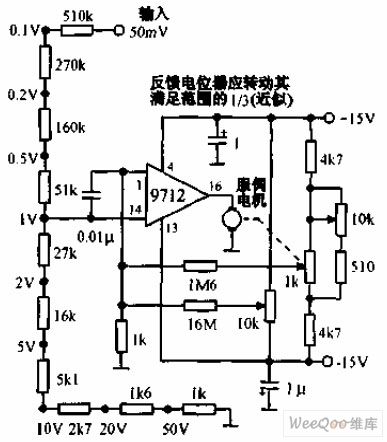
The X-Y server control circuit uses the MOSFET operational amplifier 9712 to drive the 10V, 0.2A servo motor. The servo motor can be used to confirm the position of the recording pen. The position control potentiometer has the coarse attenuation and the fine attenuation functions to the input signal. This circuit requires to use the very stable voltage-stabilized power supply.
(View)
View full Circuit Diagram | Comments | Reading(1011)
Long delay circuit 1
Published:2011/6/19 19:26:00 Author:TaoXi | Keyword: Long delay
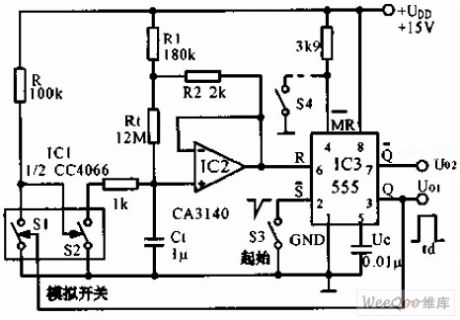
The long delay circuit is as shown in the figure, this circuit uses the 555 as the core, the high impedance op-amp CA3140 can be used as the buffer amplifier (BA), this circuit uses the bootstrapping circuit to make the charging current to maintain constant and the linearity of the charging voltage, and also the accuracy of the timing. When the pin-3 of 555 has the high electrical level, the S1 which is one of the four analog switch CC4066 conducts, the S2 cuts off, the timing capacitance C1 is charged through the R1 and Rt, the bootstrapping circuit ensures the unchanging of the R1's voltage and the charging current IC (about 10nA). So the delay time I=2UDD/3Ic=104S. S4 is the forced reset switch.
(View)
View full Circuit Diagram | Comments | Reading(584)
Stepping type servo control circuit
Published:2011/6/19 19:34:00 Author:TaoXi | Keyword: Stepping type, servo, control circuit

The stepping type servo control circuit is as shown in the figure, this circuit uses the changeable unijunction transistor (UJT) oscillator, in the control of the digital level, this oscillator produces the pulse sequence. When the logic level is 1, the oscillator produces 1000 pulses per second; when the logic level is 0, the oscillator produces 4400 pulses per second. When the logic level changes, the transition between the two pulse rate is smooth. The pulse sequence is used to start the stepping type servo motor. Q1 and Q2 are two constant current source, Q3 can be used as the voltage control resistance, it is in the parallel connection with R10 to control the pulse speed of the unijunction transistor (UJT) oscillator.
(View)
View full Circuit Diagram | Comments | Reading(611)
Two ends delay switch circuit with the LM122
Published:2011/6/19 19:40:00 Author:TaoXi | Keyword: Two ends, delay, switch

The two ends delay switch circuit with the LM122 is as shown in the figure, the LM122 integrated timer can be used as the two ends delay switch component. When the LM122 integrated timer is in the conduction state, the voltage drop is 2 to 3V, the current can be 50mA. The circuit function is: if you add the power supply voltage and after the delay time of R1C1 seconds, the relay conducts. The disconnecting current of the timer is about 3 to 4mA.
(View)
View full Circuit Diagram | Comments | Reading(485)
Server preamplifier circuit uses the parallel op-amp
Published:2011/6/19 19:50:00 Author:TaoXi | Keyword: Server, preamplifier, parallel op-amp

The server preamplifier circuit which uses the parallel op-amp is as shown in the figure, this circuit supplies the differential output to the 115V, 60Hz servo motor power amplifier. One op-amp is reversal-phase connected, another op-amp is in-phase connected to form the complementary output circuit. The voltage gain of this circuit is 40dB, and the single regulator tube supplies the power to this circuit. This circuit uses the depth DC negative feedback, so it has good DC stabilit. The bandwidth is 60KHZ, the input is drived by the 90°shifting phase.
(View)
View full Circuit Diagram | Comments | Reading(1391)
Remote control switch circuit with the infrared receiving decoding circuit
Published:2011/6/19 20:02:00 Author:TaoXi | Keyword: Remote control, switch, infrared, receiving, decoding

The infrared remote control switch circuit which uses the infrared receiving and decoding remote control circuit is as shown in the figure, the transmission circuit is composed of the astable multivibrator (composed of the 555). The oscillation frequency is about 38 kHz. The receiving circuit uses the special infrared receiving and decoding integrated circuit μPC1373H, the receiving circuit has the automatic brightness control circuit (ARC), so it has the accurate response to the infrared signals which have the different intensities and same frequencies. At this time, the output port has the low level to control the executive circuit.
(View)
View full Circuit Diagram | Comments | Reading(452)
Sound control infrared remote control switch circuit
Published:2011/6/19 20:16:00 Author:TaoXi | Keyword: Sound control, infrared remote control, switch circuit

The infrared remote control switch circuit which uses the sound control circuit BH-SK-I is as shown in the figure, the generator is the multivibrator which is composed of the 555, the output pulse drives the infrared emission diode to output the infrared pulse signal. The receing tube matches the transmitting tube, it changes the infrared pulse into the electrical signal, and this electrical signal is amplified by the BG1 to trigger the IC2 sound control integrated circuit BH-SK-I. After triggered by the BG1, the pin-12 outputs the high level to make the BG2 to conduct, and the relay closes, the socket CZ gets power. If you want to close the machine, you just need to press the button AN, the IC2's internal trigger turns to output the low level, the BG2 cuts off, the relay releases, the socket loss the electricity.
(View)
View full Circuit Diagram | Comments | Reading(713)
Infrared remote control switch circuit with the PLL audio decoding circuit
Published:2011/6/19 20:33:00 Author:TaoXi | Keyword: Infrared remote control, PLL, audio decoding

The infrared remote control switch circuit which uses the PLL audio decoding circuit is as shown in the figure, the emitter uses the multivibrator which is composed of the 555, the oscillation frequency is 1kHz to 20kHz. The receiver is composed of the infrared receiving amplifier, the audio decoder circuit and the sonic executive circuit. The infrared receiving tube needs to use with the transmitting tube. The infrared receiving amplifier is composed of the BG1 and IC1, the audio code circuit uses the audio code integrated circuit LM567 which has the phase locked loop, it requires the input signal not less than 25mV when this device is decoding, so we use the integrated power amplifier LM386 to get enough gain. The center frequency of LM567 is decided by the R5 and C7.
(View)
View full Circuit Diagram | Comments | Reading(1519)
Differential analog switch circuit
Published:2011/6/19 21:07:00 Author:TaoXi | Keyword: Differential, analog switch

The differential analog switch circuit JFET components have the tracking capability that is better than 1% in the wide temperature range. The NPD5566 dual-JFET supplies the high-accuracy signal to the differential multiplexer to reduce the deviation which is caused by the common-mode signal. The resistance value depends on the operational amplifier and the application circuit.
(View)
View full Circuit Diagram | Comments | Reading(998)
| Pages:1679/2234 At 2016611662166316641665166616671668166916701671167216731674167516761677167816791680Under 20 |
Circuit Categories
power supply circuit
Amplifier Circuit
Basic Circuit
LED and Light Circuit
Sensor Circuit
Signal Processing
Electrical Equipment Circuit
Control Circuit
Remote Control Circuit
A/D-D/A Converter Circuit
Audio Circuit
Measuring and Test Circuit
Communication Circuit
Computer-Related Circuit
555 Circuit
Automotive Circuit
Repairing Circuit