
Circuit Diagram
Index 1668
Computer Mainboard Circuit 440BX_37
Published:2011/6/26 21:26:00 Author:zj | Keyword: Computer Mainboard, 440BX_37
View full Circuit Diagram | Comments | Reading(541)
The triangular wave generator of precise amplitude adjustment
Published:2011/6/14 21:16:00 Author:Borg | Keyword: triangular wave generator, precise amplitude adjustment
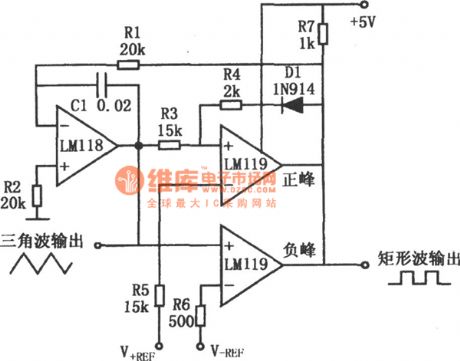
In the figure is a triangular wave generating circuit whose amplitude adjustment precision is ±0.01V. If a DC voltage is imposed on V+REF and V-REF, their amplitudes of the triangular wave are the peak the values of V+REF and V-REF, respectively. This circuit combines the integrator and two comparators which is used to judge the positive and passive peaks. If the output of the comparator on the positive terminal is positive, DI is locking on its own, and the output of the comparator on the passive peak is passive. If R1 was the potentiometer, the frequency would be changed and the amplitude is maintained. (View)
View full Circuit Diagram | Comments | Reading(539)
Computer Mainboard Circuit 440BX_38
Published:2011/6/26 21:25:00 Author:zj | Keyword: Computer Mainboard, 440BX_38
View full Circuit Diagram | Comments | Reading(469)
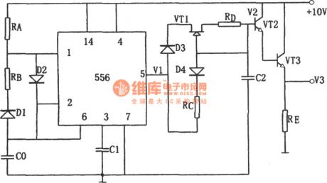
The single power supply sawtooth wave generator (556)
Published:2011/6/15 21:34:00 Author:Borg | Keyword: power supply, sawtooth wave generator
(View)
View full Circuit Diagram | Comments | Reading(826)
The sawtooth wave signal generator of D/A converter (DAC08EQ)
Published:2011/6/15 21:59:00 Author:Borg | Keyword: sawtooth wave, D/A converter
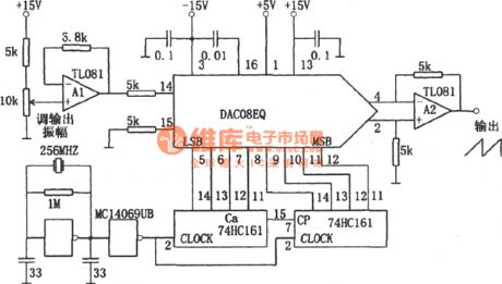
In the figure is the sawtooth wave signal generator of D/A converter. This circuit consists of the crystal oscillating circuit, counter and D/A converter. The crystal oscillating circuit delivers the signal to the counter, and the counter counts the number from 0, by each number that is counted, the D/A converter outputs an analog voltage of 1 step. When the number reaches the maximum value, it comes back to 0, and the analog comes back to 0, then the output voltage is increasing gradually, by which a precise sawtooth wave can be got. (View)
View full Circuit Diagram | Comments | Reading(675)
The multi-waveform generator of good functions
Published:2011/6/14 21:31:00 Author:Borg | Keyword: multi-waveform generator, good functions
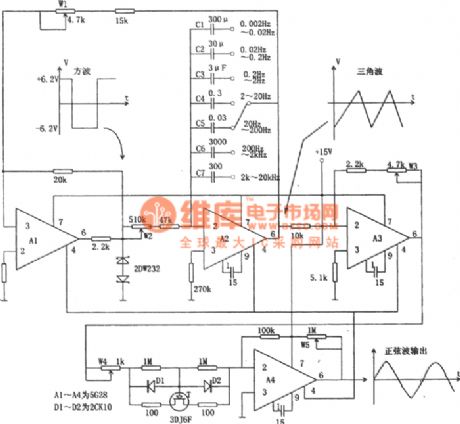
In the figure is the multi-waveform generating circuit of good functions. This circuit is fixed with 4 high impedance computing amplifiers, which can generates low-frequency, ultra-low-frequency, triangular and sine wave. In the figure, A1 functions as the voltage rectifier, A2 forms the integrator, the integration capacitor is selected by the switch. A1 and A2 are connected in a loop, which compose a typical triangular and square oscillator. The output stable pipe of A1 is used to stabilize the amplitude of the square wave, and it also increases the stability of the whole circuit. (View)
View full Circuit Diagram | Comments | Reading(603)
Computer Mainboard Circuit 440GX_11
Published:2011/6/26 21:06:00 Author:zj | Keyword: Computer Mainboard, 440GX_11
View full Circuit Diagram | Comments | Reading(504)
Computer Mainboard Circuit 440GX_10
Published:2011/6/26 21:07:00 Author:zj | Keyword: Computer Mainboard, 440GX_10
View full Circuit Diagram | Comments | Reading(491)
Computer Mainboard Circuit 440GX_09
Published:2011/6/26 21:08:00 Author:zj | Keyword: Computer Mainboard, 440GX_09
View full Circuit Diagram | Comments | Reading(437)
The linear stabilizer circuit of selectable output voltage composed of MIC5158
Published:2011/6/14 11:42:00 Author:Borg | Keyword: linear stabilizer circuit, output voltage

The simple constant current source circuit, in which MIC5158 is the controller, is shown in the figure. The output current of this circuit is mainly decided by the 35mV reference power supply voltage in MIC5158 and the external current limiting resistor Rs, their relation is I0=35mV/Rs. (View)
View full Circuit Diagram | Comments | Reading(823)
Computer Mainboard Circuit 440GX_08
Published:2011/6/26 21:09:00 Author:zj | Keyword: Computer Mainboard, 440GX_08
View full Circuit Diagram | Comments | Reading(469)
The low-noise, high-efficiency PWM step-down converting power supply composed of MAX887H
Published:2011/6/15 6:59:00 Author:Borg | Keyword: low-noise, high-efficiency, step-down

In the figure is an adjustable step-down power supply which is based on the low-noise, high-efficiency PWM and it has a few external elements. The features of the circuit are: (1) the input voltage is 3.5v~11.5v, the output voltage is 1.25v~10.25v; (2) the output current is 600mA, and the static current is 200μA. And when it is standby, the current is only 2.5μA; (3) the switching efficiency is 95%; (4) the stable working frequency of MAX887 is 300kHz, which effectively reduces the sizes and costs of the external elements. The whole circuit can be very small, which is suitable for micro-equipment. (View)
View full Circuit Diagram | Comments | Reading(774)
Computer Mainboard Circuit 440GX_07
Published:2011/6/26 21:10:00 Author:zj | Keyword: Computer Mainboard, 440GX_07
View full Circuit Diagram | Comments | Reading(528)
The 2A step-down DC switching power supply made of efficient switch controller LT1148-5
Published:2011/6/15 7:11:00 Author:Borg | Keyword: step-down, power supply, switch controller
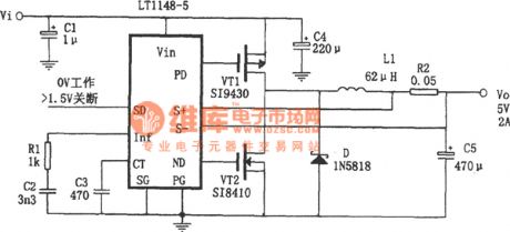
In the figure is a 2A step-down DC switching power supply made of efficient switch controller LT1148-5. The power supply circuit in fixed with MOSFET as the controlled power switch element, which replaces the external Schottky subsequent flow diode, so the voltage drop and the power consumption can be reduced further, and the switching efficiency of the power supply is increased. In the figure, if the input voltage is 6V, the loading current ranges from 20mA to 1.8A, the switching efficiency is over 95%, and the diode D functions as the protector. (View)
View full Circuit Diagram | Comments | Reading(588)
Computer Mainboard Circuit 440GX_06
Published:2011/6/26 21:11:00 Author:zj | Keyword: Computer Mainboard, 440GX_06
View full Circuit Diagram | Comments | Reading(477)
Computer Mainboard Circuit 440GX_05
Published:2011/6/26 21:14:00 Author:zj | Keyword: Computer Mainboard, 440GX_05
View full Circuit Diagram | Comments | Reading(538)
Computer Mainboard Circuit 440GX_04
Published:2011/6/26 21:16:00 Author:zj | Keyword: Computer Mainboard, 440GX_04
View full Circuit Diagram | Comments | Reading(465)
Computer Mainboard Circuit 440GX_03
Published:2011/6/26 21:19:00 Author:zj | Keyword: Computer Mainboard, 440GX_03
View full Circuit Diagram | Comments | Reading(464)
Computer Mainboard Circuit 440GX_02
Published:2011/6/26 21:21:00 Author:zj | Keyword: Computer Mainboard, 440GX_02
View full Circuit Diagram | Comments | Reading(520)
Computer Mainboard Circuit 440GX_01
Published:2011/6/26 21:21:00 Author:zj | Keyword: Computer Mainboard, 440GX_01
View full Circuit Diagram | Comments | Reading(510)
| Pages:1668/2234 At 2016611662166316641665166616671668166916701671167216731674167516761677167816791680Under 20 |
Circuit Categories
power supply circuit
Amplifier Circuit
Basic Circuit
LED and Light Circuit
Sensor Circuit
Signal Processing
Electrical Equipment Circuit
Control Circuit
Remote Control Circuit
A/D-D/A Converter Circuit
Audio Circuit
Measuring and Test Circuit
Communication Circuit
Computer-Related Circuit
555 Circuit
Automotive Circuit
Repairing Circuit


