
Circuit Diagram
Index 1665
M58655P Memory Integrated Circuit
Published:2011/6/28 7:43:00 Author:Robert | Keyword: Memory, Integrated


The M58655P is a memory IC produced by the Japanese Mitsubishi company which is widely used in TV sets, audio equipments, air conditioners and other control systems.
1.Its functional features.
The M58655P IC has internal UO buffer, data registers, memory matrix, working mode selection logic circuit, clock generater and registers, address decoding circuit and other some secondary function circuit. Its internal circuit diagram is shown in the picture.
The picture shows the M58655P IC's internal circuit diagram.
2.Its pin's functions and data.
The M58655P IC's pin's functions is shown in the picture and its working parameters is listed in the table.
The picture shows the M58655P IC's pin's functions.
The table shows the M58655 IC's working parameters. (View)
View full Circuit Diagram | Comments | Reading(1048)
Computer Mainboard Circuit 440GX_35
Published:2011/6/26 20:21:00 Author:zj | Keyword: Computer Mainboard, 440GX_35

View full Circuit Diagram | Comments | Reading(517)
M58653P Memory Integrated Circuit
Published:2011/6/28 7:52:00 Author:Robert | Keyword: Memory, Integrated


The M58653P is a memory IC produced by the Japanese Mitsubishi company which is widely used in many brands of color TV sets.
1.Its functional features.
The M58653P IC has internal data input/output interface circuit, memory matrix circuit, mode control circuit and so on.
2.Its pin's functions and data.
The M58653P IC uses 14-pin dual-in-line plastic structure. Its pin's functions are shown in the picture and its working parameters are listed in the table.
The picture shows the M58653P IC's pin's functions.
The table shows the M58653P IC's main pin's working parameters. (View)
View full Circuit Diagram | Comments | Reading(622)
Computer Mainboard Circuit 440GX_33
Published:2011/6/26 20:23:00 Author:zj | Keyword: Computer Mainboard, 440GX_33

View full Circuit Diagram | Comments | Reading(521)
Computer Mainboard Circuit 440GX_32
Published:2011/6/26 20:25:00 Author:zj | Keyword: Computer Mainboard, 440GX_32

View full Circuit Diagram | Comments | Reading(537)
KY101 IC Typical Application Circuit
Published:2011/6/28 7:57:00 Author:Robert | Keyword: IC, Typical, Application

The KY101 is a special IC for earth leakage protection which is widely used in many kinds of leakage protectors.
The earth leakage protector's typical application circuit composed of KY101 IC is shown in the picture. This circuit's static working current is about 2mA.
The picture shows the KY101 IC's typical application circuit. (View)
View full Circuit Diagram | Comments | Reading(945)
Computer Mainboard Circuit 440GX_31
Published:2011/6/26 20:26:00 Author:zj | Keyword: Computer Mainboard, 440GX_31

View full Circuit Diagram | Comments | Reading(543)
Computer Mainboard Circuit 440GX_30
Published:2011/6/26 20:27:00 Author:zj | Keyword: Computer Mainboard, 440GX_30

View full Circuit Diagram | Comments | Reading(550)
KS57C2616QFP IC Typical Application Circuit (1)
Published:2011/6/22 7:53:00 Author:Robert | Keyword: IC, Typical, Application

The KS57C2616QFP is a communication single-chip micro-computer IC which is mainly used as the mobile phone control microprocessor in the cordless telephone.
The KS57C2616QFP IC's internal part is made upof CPU, keys scanning pulse generating circuit, keys command coding circuit, clock oscillation circuit (main oscillation and displaying oscillation), charging detecting circuit, power control circuit, PLL circuit, screen displaying decoding driving circuit and so on.
The KS57C2616QFP IC uses 100-pin quatuor package and its typical application circuit is shown in the pictrue.
The picture shows the KS57C2616QFP IC's typical application circuit. (View)
View full Circuit Diagram | Comments | Reading(507)
Computer Mainboard Circuit 440GX_29
Published:2011/6/26 20:32:00 Author:zj | Keyword: Computer Mainboard, 440GX_29

View full Circuit Diagram | Comments | Reading(509)
Computer Mainboard Circuit 440GX_27
Published:2011/6/26 20:39:00 Author:zj | Keyword: Computer Mainboard, 440GX_27

View full Circuit Diagram | Comments | Reading(543)
Computer Mainboard Circuit 440GX_26
Published:2011/6/26 20:41:00 Author:zj | Keyword: Computer Mainboard, 440GX_26

View full Circuit Diagram | Comments | Reading(525)
Computer Mainboard Circuit 440GX_25
Published:2011/6/26 20:42:00 Author:zj | Keyword: Computer Mainboard, 440GX_25

View full Circuit Diagram | Comments | Reading(540)
Computer Mainboard Circuit 440GX_24
Published:2011/6/26 20:44:00 Author:zj | Keyword: Computer Mainboard, 440GX_24

View full Circuit Diagram | Comments | Reading(531)
CW9561 Analog Sound Integrated Circuit
Published:2011/6/23 6:18:00 Author:Robert | Keyword: Analog, Sound, Integrated

The CW9561 analog sound integrated circuit is a IC which can play the alarm sound, whistle sound, police cars sound and guns sound. Its typical application circuit is shown in the picture. In the circuit shown in picture (a), when the switch S2 is set separately at the position of A, B and C, this circuit would play the alarm sound, whistle sound and police cars sound. When the switch S1 is closed, the circuit would play the guns sound no matter which position the switch S2 is set. In the circuit shown in picture (b), the switch S2 is a double-pole four-throw switch. When it is set to one of the stages, the circuit would separately play the alarm sound, guns sound, ambulances sound and fire-fighting vehicle sound. (View)
View full Circuit Diagram | Comments | Reading(720)
PC mainboard circuit 430TX_29
Published:2011/6/27 20:14:00 Author:zj | Keyword: PC mainboard, 430TX_29

View full Circuit Diagram | Comments | Reading(561)
High-Accuracy Pressure Amplifying Circuit Diagram
Published:2011/6/26 9:11:00 Author:Vicky | Keyword: High-Accuracy Pressure Amplifying
High-accuracy pressure amplifying circuit is mainly used in amplifying system of small sensor output signal. AD624 is amplifying circuit of high-accuracy low-noise instrument. The above picture is a high-accuracy amplifying circuit composed of AD624, and the sensor is a standard resistance straining bridge transducer. The bridge uses voltage of + 9.00V. Potentiometers R8 and R6 are used as zero setting. R6 is coarse regulation while R8 is fine regulation. The output of the amplifier can be connected to high-accuracy A/D converter directly. The number of amplifying time in the picture is 500. The signal can be amplified by a piece of AD624. (View)
View full Circuit Diagram | Comments | Reading(685)
Typical Applied Diagram of Integrated Circuit
Published:2011/6/26 9:15:00 Author:Vicky | Keyword: Typical Applied Diagram, Integrated Circuit
Picture: Typical Applied Circuit of LM331 Integrated Circuit (View)
View full Circuit Diagram | Comments | Reading(497)
F107 Double-Power General-Type Single-Supply Amplifier Circuit Diagram
Published:2011/6/26 9:16:00 Author:Vicky | Keyword: Double-Power General-Type Single-Supply
F107 series operational amplifier is a monolithic general-type inner complementing amplifier, with relatively low input current. It has no need of exterior complementing components, and is available in integrator, and sampling/maintaining low-frequency wave generator. The analog types or substitutions are F107MT、F207LT、F307CT、F107MD、F207LD、F307CD,Fl07MJ,F207LJ、F307CJ,F307CP,SM107,SG207,SG307,LMl07,LM207,LM307 etc. (View)
View full Circuit Diagram | Comments | Reading(749)
Semiconductor Strain Gauge Structure Diagram Circuit
Published:2011/6/23 6:45:00 Author:Robert | Keyword: Semiconductor Strain Gauge, Structure, Diagram
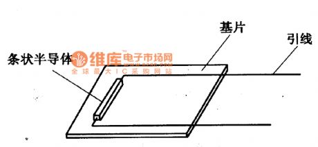
The semiconductor strain gauge is mainly produced by using the piezoresistive effect of the silicon material. If there is the force on the semiconductor crystal, the crystal would have the strain effect and also its electric resistivity would change. This phenomenon of the electric resistivity's change of the semiconductor material caused by the external force is called the piezoresistive effect of the semiconductor.
The semiconductor strain gauge is completed directly by a series of technics processes of cutting, grinding, cutting, welding wire, pasting etc. on the semiconductor material such as single crystal germanium or single crystal silicon. Its structure is shown in the picture.
The picture shows the semiconductor strain gauge structure diagram circuit. (View)
View full Circuit Diagram | Comments | Reading(1183)
| Pages:1665/2234 At 2016611662166316641665166616671668166916701671167216731674167516761677167816791680Under 20 |
Circuit Categories
power supply circuit
Amplifier Circuit
Basic Circuit
LED and Light Circuit
Sensor Circuit
Signal Processing
Electrical Equipment Circuit
Control Circuit
Remote Control Circuit
A/D-D/A Converter Circuit
Audio Circuit
Measuring and Test Circuit
Communication Circuit
Computer-Related Circuit
555 Circuit
Automotive Circuit
Repairing Circuit