
Circuit Diagram
Index 1663
The IM3886 woofer power amplifier circuit
Published:2011/6/29 5:02:00 Author:Seven | Keyword: woofer, power amplifier

The IM3886 woofer power amplifier circuit is shown as above.
(View)
View full Circuit Diagram | Comments | Reading(1267)
The OCL and OTL power supply circuit
Published:2011/6/29 4:59:00 Author:Seven | Keyword: OCL, OTL, power supply

The OCL and OTL power supply circuit is shown as above.
(View)
View full Circuit Diagram | Comments | Reading(3082)
The simple regulated circuit
Published:2011/6/29 5:03:00 Author:Seven | Keyword: regulated circuit

View full Circuit Diagram | Comments | Reading(518)
The lighting lamp power-off self-lock switch circuit
Published:2011/6/29 5:59:00 Author:Seven | Keyword: lighting lamp, self-lock switch
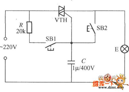
With ordinary wires controlling the lighting lamps, if the power is off, it's hard to tell whether it's ON or OFF, so it always causes the power waste when the power is on at night. If we replace the ordinary wire with the figured circuit, the weakness will be gone, which can self-lock when the power is coming back and the lamp won't be on. VTH is decided by the power of the lighting lamp, which can be the micro plastic packaged dual-way thyristor (3A/600V) of BCR3AM.
(View)
View full Circuit Diagram | Comments | Reading(442)
The money-locker or closed chamber anti-pry alarm circuit
Published:2011/6/29 6:32:00 Author:Seven | Keyword: money-locker, closed chamber, anti-pry
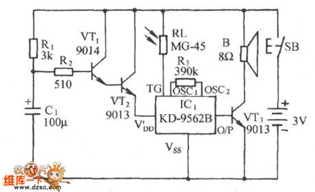
See as the figured circuit, it consists of the chamber linked switch SB, electric switch, light control sound circuit and audio amplifier, etc. If it is fixed in a closed chamber or money-locker, when the chamber or locker is pried, the circuit will make purring alarm sound, so the thief will retreat.
(View)
View full Circuit Diagram | Comments | Reading(685)
The push-pull circuit of 6P1
Published:2011/6/29 6:14:00 Author:Seven | Keyword: push-pull

The push-pull circuit of 6P1 is shown as follows.
(View)
View full Circuit Diagram | Comments | Reading(3180)
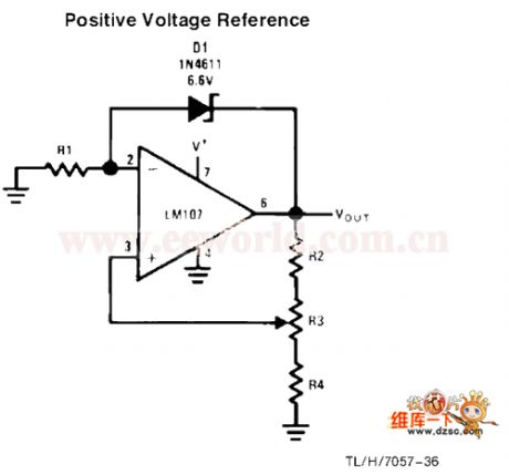
The positive voltage reference circuit
Published:2011/6/29 6:15:00 Author:Seven | Keyword: positive, voltage reference
View full Circuit Diagram | Comments | Reading(574)
FSK 433MHz Emitter Circuit Diagram
Published:2011/6/19 7:23:00 Author:Vicky | Keyword: FSK 433MHz Emitter

TH72011 applied circuit
TH71072 is a monolithic emitter chip which reaches standards of EN 300 220 and the analogs. It is available for keyless entering system, remote control/remote measuring system, data communication sysytem and security sysetem etc.
Main technical features are as follows:
·Completely integrated and stable PLL;
·Work frequency:380~450 MHz;
·Single-ended RF output;
·FSK modulation mode;
·FSK carrying out modulation driven by crystal oscillator, FSK modulation rate: DC~40 Kb/s;
·Voltage of power supply: 1.9~5.5 V;
·Work current: 3.5~10.7 mA,stand-by current 0.1μA;
·Output power: -l2~+8.5 dBm. (View)
View full Circuit Diagram | Comments | Reading(1008)
The 4-line burglar-proof alarm circuit
Published:2011/6/29 20:47:00 Author:Seven | Keyword: burglar-proof alarm
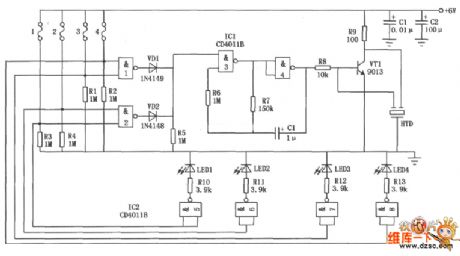
The 4-line burglar-proof alarm circuit is shown in the figure, which consists of the CD40118 integrated chips, it belongs to the multi-line burglar-proof alarm, and it can be used in 4-line burglar-proof alarm spots. It can not only make alarm sounds, but also indicate the monitored 4-line burglary in the term of LED. (View)
View full Circuit Diagram | Comments | Reading(940)
The 3-phase PWM rectifier sturcture circuit
Published:2011/6/29 6:20:00 Author:Seven | Keyword: 3-phase, PWM rectifier, sturcture circuit
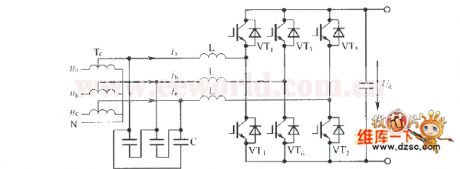
View full Circuit Diagram | Comments | Reading(1417)
The KSA100 wiring circuit of Krell classical power amplifier
Published:2011/6/29 6:22:00 Author:Seven | Keyword: wiring circuit, Krell, power amplifier

The KSA100 wiring circuit of Krell classical power amplifier is shown as above.
(View)
View full Circuit Diagram | Comments | Reading(5171)
The touched stereo circuit
Published:2011/6/29 6:37:00 Author:Seven | Keyword: touched stereo

The touched stereo circuit is shown as above.
(View)
View full Circuit Diagram | Comments | Reading(895)
ASK 440~310MHz Emitter Circuit Diagram
Published:2011/6/19 7:26:00 Author:Vicky | Keyword: ASK 440~310MHz Emitter

U2745B is a PPL emitter chips specially designed for low-cost data communication, which is available for application in wireless temperature measuring, keyless keyboard, gate lock, light, fan, air-conditioner, shutter control and other consumer products.
Main technical features are as follows:
·Emitter frequency: 310~440 MHz;
·ASK modulation mode;
·Voltge of power supply: 2.2~4 V;
·Maximum output power: 5 dBm(Vs=3 V,f=433.92 MHz,RPWRSET=l.2 kΩ);
·Maximum power dissipation: 250 mW;
·Maximum work current: l2.5 mA,maximum current udner low-power dissipation mode 10μA;
·Maximum data transfer rate: 20 Kb/s;
·Microprocessor clock signal ,which can be compatible with microcontroller such as M44C090 and M44C890;
·ESD protection (excluding pins XT02 and XT01)as requested by MIL-STD.883(4KV HBM);
·Work temperature: -20~+70℃. (View)
View full Circuit Diagram | Comments | Reading(1281)
The power-off alarm circuit of passive type
Published:2011/6/29 6:45:00 Author:Seven | Keyword: power-off, alarm circuit, passive type
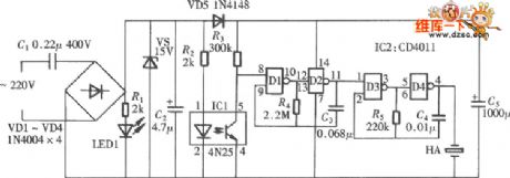
The power-off alarm of passive type doesn't mean it doesn't need a working power supply, but is makes use of the electricity in the capacitor, which allows the alarm to work for some time and complete the power-off informing task, the circuit is shown in the figure.
(View)
View full Circuit Diagram | Comments | Reading(666)
The water sound sensor application circuit
Published:2011/6/29 6:48:00 Author:Seven | Keyword: water sound sensor, application circuit
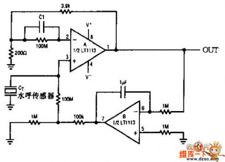
The water sound sensor application circuit is shown as above.
(View)
View full Circuit Diagram | Comments | Reading(1038)
The carbon monoxide sensor circuit
Published:2011/6/29 20:54:00 Author:Seven | Keyword: carbon monoxide, sensor
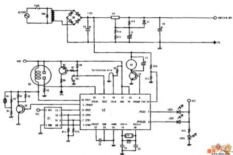
The carbon monoxide sensor circuit is shown as above.
(View)
View full Circuit Diagram | Comments | Reading(4206)
The 2.2~6V step-up circuit with the output of 7V
Published:2011/6/29 21:04:00 Author:Seven | Keyword: step-up circuit

View full Circuit Diagram | Comments | Reading(683)
The DSP connector circuit
Published:2011/6/29 7:34:00 Author:Seven | Keyword: DSP connector

The DSP connector circuit is shown in the figure.
(View)
View full Circuit Diagram | Comments | Reading(713)
The inductance oscillator circuit of 3-point type
Published:2011/6/29 21:09:00 Author:Seven | Keyword: inductance, oscillator circuit
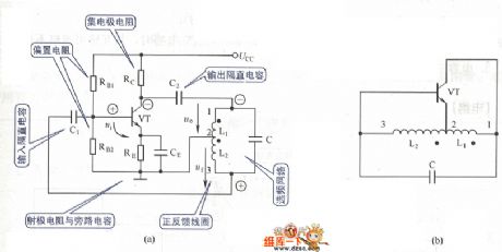
The inductance oscillator circuit of 3- point type is shown in the figure.
(View)
View full Circuit Diagram | Comments | Reading(652)
The finger touch high power sound-light alarm circuit
Published:2011/6/29 21:16:00 Author:Seven | Keyword: finger touch, high power, sound-light alarm
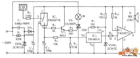
See as the figure, the circuit consists of the touch type power switch, controllable silicon trigger lamp circuit, whistle sound making circuit and audio power amplifier circuit and so on. It can be used in banks and business abodes as the emergency alarm. (View)
View full Circuit Diagram | Comments | Reading(1590)
| Pages:1663/2234 At 2016611662166316641665166616671668166916701671167216731674167516761677167816791680Under 20 |
Circuit Categories
power supply circuit
Amplifier Circuit
Basic Circuit
LED and Light Circuit
Sensor Circuit
Signal Processing
Electrical Equipment Circuit
Control Circuit
Remote Control Circuit
A/D-D/A Converter Circuit
Audio Circuit
Measuring and Test Circuit
Communication Circuit
Computer-Related Circuit
555 Circuit
Automotive Circuit
Repairing Circuit