
Circuit Diagram
Index 1669
The self-adapted adjustable stable power supply composed of LM317
Published:2011/6/14 20:23:00 Author:Borg | Keyword: self-adapted, stable power supply

In the figure is the self-adapted adjustable stable power supply composed of LM317. This power supply has LM317 as the power supply steady element, according to the voltage value, it self-shifts the circuit input voltage, by which it reduces the difference between the input voltage and output voltage, so the power consumption of the power supply is reduced. In the circuit, VT2, VD5, VW, R5, R6, C10 and the relay K compose the self-adapted shift circuit, when the output voltage V0 is lower thant 14V, VW is blocked because of the breakdown voltage is too low, and there is no current in it, VT2 is blocked, K is still, and the connector K-1 is closed, the second-stage AC current of 14V is linked to the stable circuit. (View)
View full Circuit Diagram | Comments | Reading(1731)
Computer Mainboard Circuit 440BX_39
Published:2011/6/26 21:23:00 Author:zj | Keyword: Computer Mainboard, 440BX_39

View full Circuit Diagram | Comments | Reading(476)
The voltage stable power supply used in microprocessor drive
Published:2011/6/14 21:58:00 Author:Borg | Keyword: power supply, microprocessor drive

Figure (a) is the microprocessor circuit which consists of LT1587-3.45. Figure (b) is the adjustable output voltage stable power supply which consists of LT1585. Figure (C) is the microcomputer which consists of LT1584 and LT1431. The output circuits of LT1584,LT1585 and LT1587 are 7A,4.6A and 3A, which are suitable for the stabilizer which drives the microprocessor, and they characterizes high-speed passing reaction, the loading adjustment ratio is 0.5%, there are the protection circuits in them. The basic application circuit is very easy, when stabilizing the output voltage, just connect a capacitor on the input terminal and output terminal respectively. (View)
View full Circuit Diagram | Comments | Reading(785)
Computer Mainboard Circuit 440GX_23
Published:2011/6/26 20:45:00 Author:zj | Keyword: Computer Mainboard, 440GX_23

View full Circuit Diagram | Comments | Reading(471)
The special power supply circuit(7905,7805 and 7812)
Published:2011/6/15 0:08:00 Author:Borg | Keyword: power supply

View full Circuit Diagram | Comments | Reading(3972)
Computer Mainboard Circuit 440GX_22
Published:2011/6/26 20:50:00 Author:zj | Keyword: Computer Mainboard, 440GX_22

View full Circuit Diagram | Comments | Reading(510)
Computer Mainboard Circuit 440GX_21
Published:2011/6/26 20:51:00 Author:zj | Keyword: Computer Mainboard, 440GX_21

View full Circuit Diagram | Comments | Reading(466)
The temperature compensation positive/passive symmetric stable power supply (7812、F007C)
Published:2011/6/15 1:54:00 Author:Borg | Keyword: temperature compensation, stable power supply

View full Circuit Diagram | Comments | Reading(1404)
Computer Mainboard Circuit 440GX_20
Published:2011/6/26 20:52:00 Author:zj | Keyword: Computer Mainboard, 440GX_20

View full Circuit Diagram | Comments | Reading(432)
Computer Mainboard Circuit 440GX_19
Published:2011/6/26 20:55:00 Author:zj | Keyword: Computer Mainboard Circuit 440GX_19

View full Circuit Diagram | Comments | Reading(479)
Computer Mainboard Circuit 440GX_18
Published:2011/6/26 20:56:00 Author:zj | Keyword: Computer Mainboard, 440GX_18

View full Circuit Diagram | Comments | Reading(504)
The practical precise adjustable power supply
Published:2011/6/15 2:00:00 Author:Borg | Keyword: adjustable power supply

View full Circuit Diagram | Comments | Reading(945)
Computer Mainboard Circuit 440GX_17
Published:2011/6/26 20:57:00 Author:zj | Keyword: Computer Mainboard, 440GX_17

View full Circuit Diagram | Comments | Reading(505)
Computer Mainboard Circuit 440GX_16
Published:2011/6/26 20:57:00 Author:zj | Keyword: Computer Mainboard, 440GX_16

View full Circuit Diagram | Comments | Reading(486)
Adjusting W317 stabilizer from zero
Published:2011/6/15 23:19:00 Author:Borg | Keyword: stabilizer

One of the differences between this circuit and W317 basic application circuit is that there is a team of passive voltage affiliated power supply in the circuit. The voltage on the stabilizer pipe DW positive pole to the earth is -1.25v, the lower terminal of the voltage adjusting potentiometer is not connected with the earth but with the positive pole of the pipe, the output voltage of the stable power supply is still got from the part between the output pole and earth of the 3-terminal stabilizer. So when the resistance of W is regulated to 0, the 1.25v voltage on R1 offsets the -1.25v voltage on DW, which makes the output voltage be 0v. (View)
View full Circuit Diagram | Comments | Reading(680)
Computer Mainboard Circuit 440GX_15
Published:2011/6/26 21:01:00 Author:zj | Keyword: Computer Mainboard, 440GX_15

View full Circuit Diagram | Comments | Reading(455)
Computer Mainboard Circuit 440GX_14
Published:2011/6/26 21:02:00 Author:zj | Keyword: Computer Mainboard, 440GX_14

View full Circuit Diagram | Comments | Reading(441)
Computer Mainboard Circuit 440GX_13
Published:2011/6/26 21:03:00 Author:zj | Keyword: Computer Mainboard, 440GX_13

View full Circuit Diagram | Comments | Reading(469)
The medical call receiver circuit with lighting signals
Published:2011/6/15 21:11:00 Author:Borg | Keyword: call receiver, lighting signals
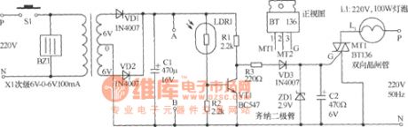
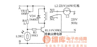
In the figure is a receiver that can avoid leaving out the sound of asking for help, in the daytime, only the receiver works and the lights automatically cut off. At night, the receiver and the lights can be sent out with the request of the patients. When the calling key is pressed, the primary stage of transformer X1 is also connected with the AC power supply at the same time, and after being rectified and filtered, the power supply of the second stage outputs a DC voltage which is delivered to the collecting electrode of VT1 by R1. If it is the daytime, due to the rays, LDR1 is in a low resistance, VT1 is conducting, and the collecting electrode is reduced to the earth connection.
(View)
View full Circuit Diagram | Comments | Reading(843)
Computer Mainboard Circuit 440GX_12
Published:2011/6/26 21:05:00 Author:zj | Keyword: Computer Mainboard, 440GX_12

View full Circuit Diagram | Comments | Reading(470)
| Pages:1669/2234 At 2016611662166316641665166616671668166916701671167216731674167516761677167816791680Under 20 |
Circuit Categories
power supply circuit
Amplifier Circuit
Basic Circuit
LED and Light Circuit
Sensor Circuit
Signal Processing
Electrical Equipment Circuit
Control Circuit
Remote Control Circuit
A/D-D/A Converter Circuit
Audio Circuit
Measuring and Test Circuit
Communication Circuit
Computer-Related Circuit
555 Circuit
Automotive Circuit
Repairing Circuit