
Circuit Diagram
Index 1674
The standby power supply control circuit
Published:2011/6/28 20:56:00 Author:qqtang | Keyword: standby, power supply control

View full Circuit Diagram | Comments | Reading(653)
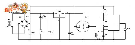
The breeze ceiling fan temperature control circuit
Published:2011/6/28 21:12:00 Author:qqtang | Keyword: ceiling fan, temperature control
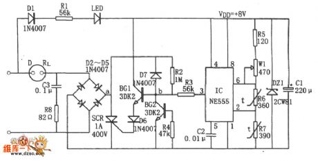
In the figure is the breeze ceiling fan temperature control circuit which consists of the temperature detection circuit and step-down rectifier power supply. In the circuit, the power supply provides with VDD=+5V DC voltage for the control circuit. The temperature detection control circuit is the dual steady trigger whose core is composed of IC(555), R5, R7, W1 and R6, and R6 and R7 is adopted with the NTC thermistor as the temperature detection element.When the environment temperature is rising, the resistance of R6 and R7 is falling down, which makes the IC to be reset because the LEV of 2-pin is dropping to 1/3VDD, and 3-pin is outputting a high LEV.
(View)
View full Circuit Diagram | Comments | Reading(1638)
The precise temperature control circuit of temperature/frequency converter
Published:2011/6/28 21:29:00 Author:qqtang | Keyword: temperature control, temperature/frequency converter
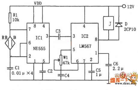
In the figure is the precise temperature control circuit of temperature/frequency converter, which consists of the temperature sensor B, multi-resonance oscillator, audio decoder and relay, etc. The oscillator consists of IC1(555), R1, C1 and the temperature sensor, whose oscillating frequency is fc=1.44/(Rl+2RB)C1. As RB changes with the temperature, so fs also changes with the temperature. The audio decoder is adopted with the audio decoding integrated circuit IC2(LM567) with phase-lock, whose central frequency is fo=1/1.1Rw1C4, by adjusting W1, fo is the frequency of setting temperature.
(View)
View full Circuit Diagram | Comments | Reading(878)
The electric oven temperature control circuit of single phase controllable silicon zero passage trigger
Published:2011/6/28 21:55:00 Author:qqtang | Keyword: electric oven, temperature control, controllable silicon
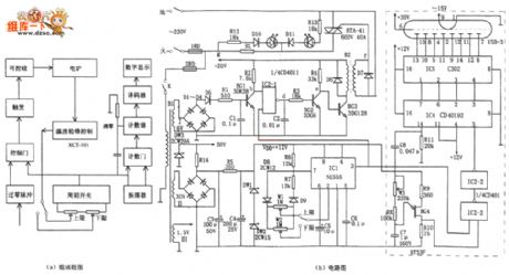
In the figure is the electric oven temperature control circuit of single phase controllable silicon zero passage trigger. This temperature control device consists of the detecting temperature control circuit, zero passage detection circuit, period switch, trigger control and digital display, etc. It is often used with XCT-101 temperature controller, which can monitor the 6~8kW electric oven temperature of single phase controllable silicon zero passage trigger, both temperature rising and dropping are adjusted within 1%~99%. The temperature control device XCT~101 detects the oven internal temperature with thermocouple and compares the real temperature with the preset temperature.
(View)
View full Circuit Diagram | Comments | Reading(2772)
The incubation temperature control circuit
Published:2011/6/28 22:11:00 Author:qqtang | Keyword: incubation, temperature control
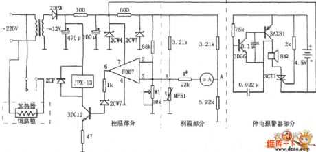
In the figure is the incubation temperature control circuit. This circuit consists of the temperature test circuit, temperature control circuit and power-off alarm circuit, etc.the temperature circuit is a non-equilibrium type bridge, which is indicated with a 50μA meter. One arm of the bridge is a sensitive thermistor MF51 which has backward temperature coefficients. As the temperature in the incubation box changes, the resistance of MF51 is also changing, the LEV between A and B of the corresponding bridge is changing, too. The temperature change is reflected by the pointer of the 50ttA meter.
(View)
View full Circuit Diagram | Comments | Reading(1215)
Bean sprout machine thermostat controller circuit diagram
Published:2011/6/14 3:11:00 Author:Lucas | Keyword: Bean sprout machine, thermostat controller
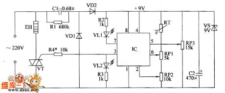
The bean sprout machine thermostat controller circuit is composed of the power supply circuit and temperature detection control circuit, and the circuit is shown as the chart. The power supply circuit is composed of the drain resistor R1, rectifier diodes VD1, VD2, power regulator diode VS, buck capacitor C1, filter capacitor C2. Temperature detection control circuit is composed of the thermistor RT, potentiometers RP1 ~ RP3, resistors R2 ~ R4, VT and heating wire EH. AC 220V voltage bucked by C1, rectified by VD1 and VD2, stabilized by VS and filtered by C2 can provide +9 V voltage for IC. R1 ~ R4 select 1/2W metal film resistors. RP1 ~ RP3 use synthetic membrane potentiometers. VD1 and VD2 select 1N4007 silicon rectifier diodes.
(View)
View full Circuit Diagram | Comments | Reading(1981)
Bean sprouts automatic watering thermostats circuit diagram
Published:2011/6/14 3:03:00 Author:Lucas | Keyword: Bean sprouts , automatic watering , thermostats
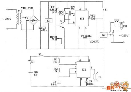
The bean sprouts automatic watering thermostats circuit is composed of the power supply circuit, temperature detection control circuit and power failure alarm circuit, and the circuit is shown as the chart. Temperature detection control circuit is composed of the thermistor RT, potentiometers RP1 ~ RP3, transistor V, time-base integrated circuit IC1 and capacitor C2, diodes VD5, VD6, relay K2 and the control switch S1 . Power failure alarm circuit consists of the relay K1, switch S2, resistors R1, R2, capacitors C3, C4, and speaker BL and the time-base integrated circuit IC2. R1 and R2 use 1/4W carbon film resistors or metal film resistors. RP1 ~ RP3 use small organic solid potentiometers or variable resistors. RT chooses the thermistor resistor with negative temperature coefficient.
(View)
View full Circuit Diagram | Comments | Reading(884)
Plastic bag sealing machine circuit diagram 3
Published:2011/6/14 2:57:00 Author:Lucas | Keyword: Plastic bag , sealing machine


The plastic bag sealing machine circuit is composed of power supply circuit, heating control circuit and indicating circuit, and the circuit is shown as the chart. Power supply circuit is composed of the power switch S1, power transformer T, rectifier diode VD1, filter capacitor C1, resistor R1 and the current limiting voltage regulator diode VS. Heating control circuit consists of resistors R2 ~ R4, potentiometer RP, capacitor C2, transistors V1, V2, relay K, diode VD2, control switch S2, heater EH. Indicating circuit is composed of the power light HL1, working status indicator HL2, resistor R5, capacitor C3, transistor V3, and the normally open contact K2 of K. R1 ~ R5 use 1/4W carbon film resistors or metal film resistors.
(View)
View full Circuit Diagram | Comments | Reading(5342)
Electronic fishing shrimp machine circuit diagram 2
Published:2011/6/14 4:00:00 Author:Lucas | Keyword: Electronic , fishing shrimp machine

The ectronic fishing shrimp machine circuit is composed of the astable oscillator, inverter circuit, high voltage output circuit, and the circuit is shown as the figure 20. Astable oscillator circuit is composed of the time-base integrated circuit IC, resistors R3, R4, potentiometer RP2, diodes VD4, VD5 and capacitors C4, C5. Inverter circuit is composed of the transistors V1, V2, transformers T1, T2, resistor R1, potentiometer RP1, diode VD3 and capacitor C3. High-voltage output circuit consists of the transformer T2, relay K, diodes VD1, VD2, VD6, resistor R2, capacitors C1, C2, neon light HL and the electrodes A, B. Adjusting the resistance of RP1 can change the oscillation frequency of the inverter circuit.
(View)
View full Circuit Diagram | Comments | Reading(10170)
Electronic fishing shrimp machine circuit diagram 1
Published:2011/6/14 3:55:00 Author:Lucas | Keyword: Electronic, fishing shrimp machine

The electronic fishing shrimp machine circuit is composed of more than two multivibrators and high voltage generating circuit, and the circuit is shown as the chart. The low-frequency multivibrator is composed of one time-base IC of the dual time-base IC and resistors R1, R2, capacitors C1, C2, LED VL1, potentiometers RP1, RP2. When the oscillator works, VL1 shines. The high-frequency multivibrator is composed of the other time-base IC of the dual time-base IC and resistors R3, R4, light-emitting diode VL2, potentiometer RP3, capacitors C3, C4 and other components. When the oscillator works, VL2 shines. High-voltage generating circuit consists of the VM0S field-effect transistors VF1, VF2, resistors R7 ~ R11, Zener diode VS and step-up transformer T and so on.
(View)
View full Circuit Diagram | Comments | Reading(3875)
Greenhouse ground hotline controller circuit diagram 2
Published:2011/6/14 5:20:00 Author:Lucas | Keyword: Greenhouse, ground hotline , controller
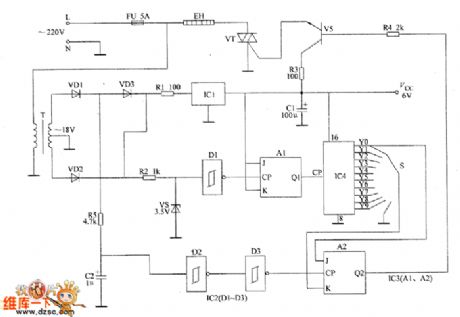
The greenhouse ground hotline controller circuit is composed of the power supply circuit and heating control circuit, and the circuit is shown as the chart. Power supply circuit is composed of the fuse FU, power transformer T, rectifier diodes VD1 ~ VD3, resistor R1, three-terminal voltage regulator integrated circuit IC and the filter capacitor C1. Heating control circuit is composed of the resistors R2 ~ R5, capacitor C2, voltage regulator diode VS, Schmitt trigger NAND gate integrated circuit IC2 (D1 ~ D3), JK flip-flop integrated circuit IC3 (A1, A2), count / pulse divider IC IC4, selector switch S, transistor V, thyristor VT and ground hotline EH. R1 ~ R3 and R5 select 1/2W metal film resistors.
(View)
View full Circuit Diagram | Comments | Reading(1117)
Greenhouse ground hotline controller circuit diagram 1
Published:2011/6/14 5:15:00 Author:Lucas | Keyword: Greenhouse, ground hotline, controller
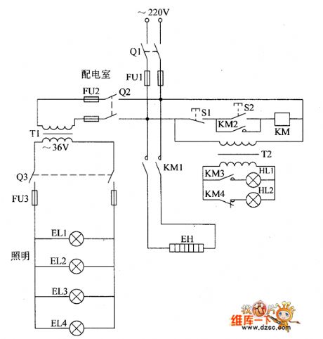
The greenhouse ground hotline controller circuit is composed of the power supply control circuit, working status indicator circuit and low voltage lighting circuit, and the circuit is shown as the chart. Control circuit is composed of the knife switch Q1, fuse FU1, control buttons S1, S2, AC contactor KM and ground hotline EH. Working status indicator circuit consists of the power transformer T1, lights HL1, H12, and the control contacts KM3, KM4 of KM. Low-voltage lighting circuit is composed of the power transformer T1, knife switches Q2, 03, fuses FU2, FU3 and lighting lamps EL1 ~ EL4. KM chooses CDC10-5 220V AC contactor. Q1 chooses HK2-30 Q1 knife switch; Q7 and Q3 use HK1-15 knife switches.
(View)
View full Circuit Diagram | Comments | Reading(1109)
The electronic rodent repeller circuit diagram 4
Published:2011/6/14 20:31:00 Author:Lucas | Keyword: Electronic rodent repeller

The electronic rodent repeller circuit is composed of the high voltage generating circuit and music alarm circuit, and the circuit is shown as the chart. High-voltage generating circuit is composed of the power switch S, light EL, indicator light HL, power transformer T, relay K and high voltage power grid. Music alarm circuit is composed of the music integrated circuit IC, transistor V, capacitors C1, C2, diodes VD1 ~ VD4 and speaker BL. Turning on the power switch S will make AC 220V voltage be limited by EL, transformed by T. And then it will generate 2kV high AC voltage on the winding W2 of T, and the voltage is added on high voltage electrified wire netting by the relay K; W3 winding generates 3.5V AC voltage and rectified by the VD1 ~ VD4, filtered by C1 to provide operating voltage for the IC at the same time of HL being lit.
(View)
View full Circuit Diagram | Comments | Reading(947)
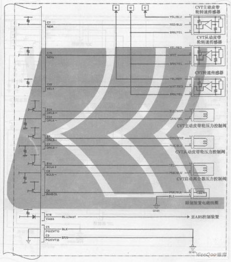
GuangZhou HONDA Fit saloon car engine circuit 8
Published:2011/6/19 19:01:00 Author:TaoXi | Keyword: GuangZhou, HONDA, Fit, saloon car, engine circuit
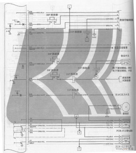
GuangZhou HONDA Fit saloon car engine circuit (View)
View full Circuit Diagram | Comments | Reading(457)
GuangZhou HONDA Fit saloon car engine circuit 5
Published:2011/6/19 19:02:00 Author:TaoXi | Keyword: GuangZhou, HONDA, Fit, saloon car, engine circuit
GuangZhou HONDA Fit saloon car engine circuit (View)
View full Circuit Diagram | Comments | Reading(412)
Intelligent lock control balcony alarm bell circuit diagram
Published:2011/6/20 6:36:00 Author:Lucas | Keyword: Intelligent, lock control , balcony , alarm bell
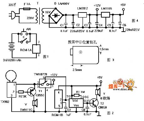
Figure 1 is a transmitter circuit which is installed at the gate. AN is the doorbell button, and K is the lock control switch; when all the family goes out and locks the check-lock for insurance, the K connected automatically to play the role of fortification. When people press the AN or connect K, RCM-1A will launch 250 ~ 300MHz radio wave by modulation, Figure 2 is a receiver circuit, which is installed in the balcony ceiling, and RCM-1B can receive the modulation radio waves and pin 2 output is in high level, thereby it triggers the language IC to work.
(View)
View full Circuit Diagram | Comments | Reading(1107)
Battery charging protection circuit composed of the PTC component and the over-voltage protection component
Published:2011/6/28 19:08:00 Author:TaoXi | Keyword: Battery charging, protection circuit, PTC component, over-voltage protection component
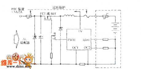
The PTC component and the over-voltage protection component harmonize to complete the following jobs: 1.Supply the current protection for the FET which might be damaged and the battery's excessive current. 2. The PTC limits the over-current which is produced by the forward direction conduction of the Zener diode. 3. Limit the conduction current when the over-voltage component is protecting the voltage overload.
(View)
View full Circuit Diagram | Comments | Reading(664)
Gas / smoke alarm circuit diagram
Published:2011/6/14 3:29:00 Author:Lucas | Keyword: Gas, smoke , alarm
The gas / smoke alarm circuit is shown in Figure, and it is composed of the power supply circuit, sensor and multivibrator. One way of the 220V mains electricity bucked by the transformer, rectified by full bridge, filtered by capacitor and through the three-terminal voltage regulator can provide +S V voltage for the gas sensor, the other way can directly supply multivibrator speaker. Sensor uses QM-N 5 or QM 211 type. It is a relatively strong universal gas sensor which is suitable for the smoke and fire caused by natural gas, coal gas, LPG, gasoline, carbon monoxide, hydrogen, alkanes, alcohols, and wood, paper; cloth, hair products, rubber products, plastic products and oil and so on.
(View)
View full Circuit Diagram | Comments | Reading(854)
Vizi saloon car electric window and central lock circuit
Published:2011/6/28 19:17:00 Author:TaoXi | Keyword: Vizi, saloon car, electric window, central lock

Vizi saloon car electric window and central lock circuit is as shown in the figure:
(View)
View full Circuit Diagram | Comments | Reading(517)
AN7222 frequency modulation & amplitude modulation power amplifier integrated circuit
Published:2011/6/28 2:48:00 Author:Christina | Keyword: frequency modulation, amplitude modulation, power amplifier, integrated circuit


The AN7222 is designed as one kind of frequency modulation & amplitude modulation power amplifier integrated circuit that can be used in all kinds of audio system radio circuits such as the home audio and car audio systems.
1.Features
The AN7222 has the AM detection and FM detection circuits, both of them have the level driver circuit; it has the automatic frequency control function, because of the AM high frequency amplifier, the sensitivity is good, the power consumption is low, and the external components are few. The internal circuit block diagram is as shown in figure.
Figure 1 The internal circuit block diagram of AN7222
2.Pin functions and data
The AN7222 uses the 18-pin dual-row DIP package, the pin functions and data are as shown in table 1.
Table 1 The pin functions and data of the AN7222
3.The typical application circuit of the AN7222
(View)
View full Circuit Diagram | Comments | Reading(4315)
| Pages:1674/2234 At 2016611662166316641665166616671668166916701671167216731674167516761677167816791680Under 20 |
Circuit Categories
power supply circuit
Amplifier Circuit
Basic Circuit
LED and Light Circuit
Sensor Circuit
Signal Processing
Electrical Equipment Circuit
Control Circuit
Remote Control Circuit
A/D-D/A Converter Circuit
Audio Circuit
Measuring and Test Circuit
Communication Circuit
Computer-Related Circuit
555 Circuit
Automotive Circuit
Repairing Circuit