Temperature Control
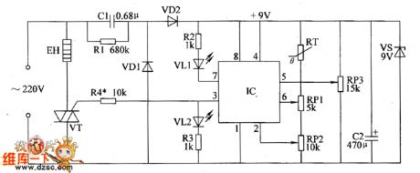
Bean sprout machine thermostat controller circuit diagram
Published:2011/6/14 3:11:00 Author:Lucas | Keyword: Bean sprout machine, thermostat controller | From:SeekIC

The bean sprout machine thermostat controller circuit is composed of the power supply circuit and temperature detection control circuit, and the circuit is shown as the chart. The power supply circuit is composed of the drain resistor R1, rectifier diodes VD1, VD2, power regulator diode VS, buck capacitor C1, filter capacitor C2. Temperature detection control circuit is composed of the thermistor RT, potentiometers RP1 ~ RP3, resistors R2 ~ R4, VT and heating wire EH. AC 220V voltage bucked by C1, rectified by VD1 and VD2, stabilized by VS and filtered by C2 can provide +9 V voltage for IC. R1 ~ R4 select 1/2W metal film resistors. RP1 ~ RP3 use synthetic membrane potentiometers. VD1 and VD2 select 1N4007 silicon rectifier diodes.
Reprinted Url Of This Article:
http://www.seekic.com/circuit_diagram/Control_Circuit/Temperature_Control/Bean_sprout_machine_thermostat_controller_circuit_diagram.html
Print this Page | Comments | Reading(3)

Article Categories
power supply circuit
Amplifier Circuit
Basic Circuit
LED and Light Circuit
Sensor Circuit
Signal Processing
Electrical Equipment Circuit
Control Circuit
Remote Control Circuit
A/D-D/A Converter Circuit
Audio Circuit
Measuring and Test Circuit
Communication Circuit
Computer-Related Circuit
555 Circuit
Automotive Circuit
Repairing Circuit
Code: