Alarm Control
Intelligent lock control balcony alarm bell circuit diagram
Published:2011/6/20 6:36:00 Author:Lucas | Keyword: Intelligent, lock control , balcony , alarm bell | From:SeekIC

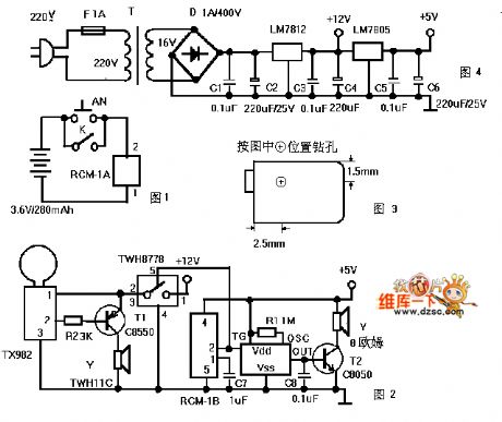
Figure 1 is a transmitter circuit which is installed at the gate. AN is the doorbell button, and K is the lock control switch; when all the family goes out and locks the check-lock for insurance, the K connected automatically to play the role of fortification. When people press the AN or connect K, RCM-1A will launch 250 ~ 300MHz radio wave by modulation, Figure 2 is a receiver circuit, which is installed in the balcony ceiling, and RCM-1B can receive the modulation radio waves and pin 2 output is in high level, thereby it triggers the language IC to work.
Reprinted Url Of This Article:
http://www.seekic.com/circuit_diagram/Control_Circuit/Alarm_Control/Intelligent_lock_control_balcony_alarm_bell_circuit_diagram.html
Print this Page | Comments | Reading(3)

Article Categories
power supply circuit
Amplifier Circuit
Basic Circuit
LED and Light Circuit
Sensor Circuit
Signal Processing
Electrical Equipment Circuit
Control Circuit
Remote Control Circuit
A/D-D/A Converter Circuit
Audio Circuit
Measuring and Test Circuit
Communication Circuit
Computer-Related Circuit
555 Circuit
Automotive Circuit
Repairing Circuit
Code: