
Circuit Diagram
Index 1673
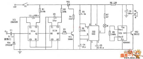
555 TV automatic shutdown controller circuit
Published:2011/6/15 3:13:00 Author:TaoXi | Keyword: 555, TV, automatic, shutdown, controller
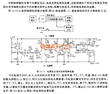
The principle block diagram of the controller is as shown in figure 14-15(a), figure(b) is the circuit. The C1 is connected with the A point of the TV's sync separation stage.
When there is the TV signals, the sync signal from point A conducts the VT1, then VT2 and VT3 conduct to set the trigger which is composed of 555, the JB and J1 closes to turn on the TV's power supply; when the TV program is over, the sync signal disappears, so VT2 and VT2 cut off. The charged C2 discharges through the emitters of R5 and VT3 to keep the VT3 in the conduction state for 10 seconds, so that we can avoid the shut-down phenomenon which is caused by the programme-delivery intermittent or the replacing. After the VT3 cuts off, pin-6 of 555 has the high electrical level to reset 555, JB releases to cut off the TV's power supply.
(View)
View full Circuit Diagram | Comments | Reading(654)
Ball Game Scoring Device (CD4027,CD4055,CD40192) Circuit Diagram
Published:2011/6/25 10:39:00 Author:Vicky | Keyword: Ball Game Scoring Device

Ball game scoring device’s circuit is as shown in the picture. It is used to record and display the performance of a ball game. The first Nixie tube has only two states, that is extinguishing or displaying “1”; the next two Nixie tube can display ten states from 0 to 9. Therefore, the maximum scoring of the scoring machine can reach 199. The circuit is mainly composed of scoring circuit, decoding circuit, trigger decode, displaying circuit and anti-vibration switch circuit. (View)
View full Circuit Diagram | Comments | Reading(6106)
Telephone Voice Recorder (CD4511B, VCD4518B) Circuit Diagram
Published:2011/6/25 10:42:00 Author:Vicky | Keyword: Telephone Voice Recorder

Telephone voice recorder circuit is as shown in the picture. It is mainly used to record and display the numbers that the telephone is used in one day to help people get to know the usage situation of the telephone. The recorder is composed of two seven-segment Nixie tube, therefore the maximum recording number is up to 99. There is reset button in the circuit which can clear the records. (View)
View full Circuit Diagram | Comments | Reading(1931)
Proximity Detector (LM385) Diagram Circuit
Published:2011/6/26 18:56:00 Author:Vicky | Keyword: Proximity Detector
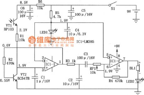
Proximity detector circuit is shown in the above picture. The circuit adopts ordinary phototube to detect the illumination changes when people enters alert zones, and thereby realize detecting function. (View)
View full Circuit Diagram | Comments | Reading(1980)
Motor Operation Control Circuit of LT1014
Published:2011/6/25 22:44:00 Author:Michel | Keyword: Motor, Operation , Control Circuit
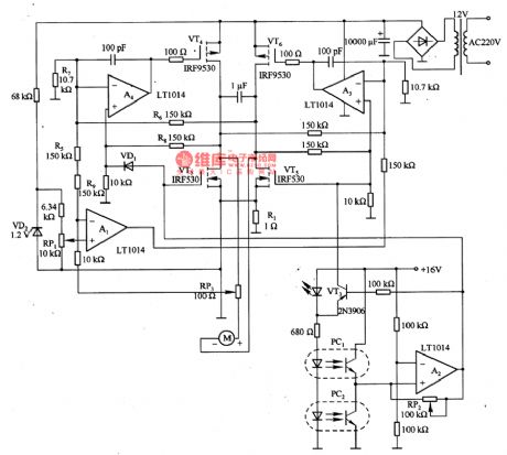
The aboved picture is motor operation control circuit compsoed of LT0140 etc.Motor speed voltage is set by middle tap of potentiometer RP1.In order to make the motor speed stable, RP3 adjusts the positive feedback voltgae from current detection resistance R1 is inversely proportional to the current and A1 adds the feedback voltage and speed setting voltage together.The best RP3 adjustment can completely offset the motor parasitic resistance, so that motor torque-speed characteristics are hard.Motor speed control performance does not depend on mechanical loading, but driving circuit voltage. (View)
View full Circuit Diagram | Comments | Reading(916)
The principle diagram of the sound control switch and amplifier circuit
Published:2011/6/27 20:23:00 Author:Borg | Keyword: principle diagram, sound control switch, amplifier circuit

View full Circuit Diagram | Comments | Reading(672)
MB3752 adjustable regulator, main features and pin of DC-DC circuit and power supply monitor
Published:2011/6/21 6:41:00 Author:Lucas | Keyword: adjustable, regulator, main features , pin , DC-DC , power supply monitor

MB3752 adjustable regulator(positive output)
The regulator has the adjustable output voltage; output voltage range is 2.0 ~ 37V; Output Current is 1 ~ 50mA; input voltage range is9.0 ~ 40V; dual in-line ceramic seal function is 1000mW, plastic dual in-line function is 800mW, SO plastic is 620mW; ceramic seal operating temperature is -55 ~ +125 ℃, plastic seal is -20 ~ +75 ℃; it contains over-current protection circuit.
(View)
View full Circuit Diagram | Comments | Reading(497)
The application circuit diagram of capacitive sensor signal regulator
Published:2011/6/27 4:45:00 Author:Ecco | Keyword: application circuit , capacitive sensor, signal regulator

Typical application circuit of CS2001 is shown as the chart. The picture (A) shows the wiring circuit of ± 2.5V dual power supply, and (b) shows the wiring circuit of single +5 V power supply. C3, C4 are decoupling capacitors. In the figure (C), CF is the capacitor for adjusting the bandwidth, and RP is potentiometer to adjust the gain. The output voltage of CS2001 is leaded from Uo, AGND end and connected to the digital voltmeter (DVM).
(View)
View full Circuit Diagram | Comments | Reading(696)
MC34063 step-down expansion flow designing circuit diagram
Published:2011/6/28 2:33:00 Author:Ecco | Keyword: step-down , expansion flow, designing

View full Circuit Diagram | Comments | Reading(5869)
Antig 15 W electronic ballast circuit diagram
Published:2011/6/28 2:24:00 Author:Ecco | Keyword: Antig, 15 W , electronic ballast

View full Circuit Diagram | Comments | Reading(1007)
40 W electronic ballast electric principle circuit diagram
Published:2011/6/28 2:21:00 Author:Ecco | Keyword: 40 W , electronic , ballast, electric principle

View full Circuit Diagram | Comments | Reading(1578)
A single pipe electronic ballast circuit diagram
Published:2011/6/28 2:54:00 Author:Ecco | Keyword: single pipe , electronic ballast

View full Circuit Diagram | Comments | Reading(1387)
MP3 charger circuit diagram
Published:2011/6/28 2:56:00 Author:Ecco | Keyword: MP3 charger

View full Circuit Diagram | Comments | Reading(595)
LA4192 audio IC circuit diagram
Published:2011/6/28 2:42:00 Author:Ecco | Keyword: audio IC

View full Circuit Diagram | Comments | Reading(3283)
LA4190 audio IC circuit diagram
Published:2011/6/28 2:42:00 Author:Ecco | Keyword: audio IC

View full Circuit Diagram | Comments | Reading(1481)
The package model and pin arrangement circuit of ATCI05
Published:2011/6/28 20:19:00 Author:qqtang | Keyword: package model, pin arrangement

View full Circuit Diagram | Comments | Reading(530)
The multi-way alarm monitor circuit
Published:2011/6/28 20:28:00 Author:qqtang | Keyword: multi-way, alarm monitor
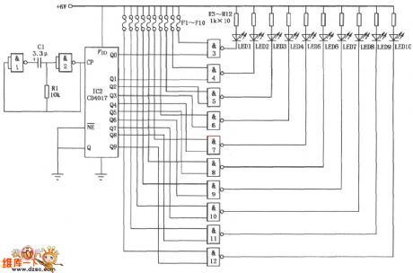
The multi-way alarm monitor circuit is shown in the figure. It consists of the integrated circuits of CD401 and CD4017, and it is used in indicator alarm and monitoring. This circuit can do circle monitoring to 10 spots, once the burglary happened at on spot, the LED monitoring station fixed in the duty room would get corresponding alarm signal.
(View)
View full Circuit Diagram | Comments | Reading(536)
The internal circuit of voltage monitoring integrated chip TL7705CP
Published:2011/6/28 20:37:00 Author:qqtang | Keyword: internal circuit, voltage monitoring

View full Circuit Diagram | Comments | Reading(731)
The metal door prying resistant alarm circuit
Published:2011/6/28 20:41:00 Author:qqtang | Keyword: prying resistant, alarm circuit
The metal door prying resistant alarm circuit is shown in the circuit. This circuit consists of the CD4528、NE555 and KD9561 integrated circuit and other external elements. The circuit control is sensitive and it's adjustable, it's also reliable and low-cost.
(View)
View full Circuit Diagram | Comments | Reading(549)
The thermoregulation heater circuit
Published:2011/6/28 20:55:00 Author:qqtang | Keyword: thermoregulation heater

The thermoregulation heater circuit is shown in the figure. It is divided into off , Lo AND HL 3 gears. When the converting switch is pulled from SA to Lo, the 220V mains is added on the two terminals of loading RL by VD4 and VD56; due to the half-wave rectification of the diode, the working voltage of RL is obviously lower than that when the 220v current is passable directly, so the temperature of RL is falling down.
(View)
View full Circuit Diagram | Comments | Reading(607)
| Pages:1673/2234 At 2016611662166316641665166616671668166916701671167216731674167516761677167816791680Under 20 |
Circuit Categories
power supply circuit
Amplifier Circuit
Basic Circuit
LED and Light Circuit
Sensor Circuit
Signal Processing
Electrical Equipment Circuit
Control Circuit
Remote Control Circuit
A/D-D/A Converter Circuit
Audio Circuit
Measuring and Test Circuit
Communication Circuit
Computer-Related Circuit
555 Circuit
Automotive Circuit
Repairing Circuit