Control Circuit
555 TV automatic shutdown controller circuit
Published:2011/6/15 3:13:00 Author:TaoXi | Keyword: 555, TV, automatic, shutdown, controller | From:SeekIC

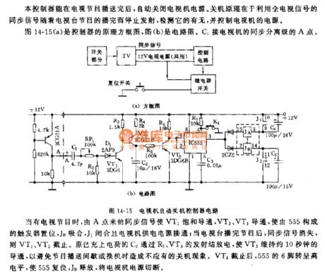
The principle block diagram of the controller is as shown in figure 14-15(a), figure(b) is the circuit. The C1 is connected with the A point of the TV's sync separation stage.
When there is the TV signals, the sync signal from point A conducts the VT1, then VT2 and VT3 conduct to set the trigger which is composed of 555, the JB and J1 closes to turn on the TV's power supply; when the TV program is over, the sync signal disappears, so VT2 and VT2 cut off. The charged C2 discharges through the emitters of R5 and VT3 to keep the VT3 in the conduction state for 10 seconds, so that we can avoid the shut-down phenomenon which is caused by the programme-delivery intermittent or the replacing. After the VT3 cuts off, pin-6 of 555 has the high electrical level to reset 555, JB releases to cut off the TV's power supply.
Reprinted Url Of This Article:
http://www.seekic.com/circuit_diagram/Control_Circuit/555_TV_automatic_shutdown_controller_circuit.html
Print this Page | Comments | Reading(3)

Article Categories
power supply circuit
Amplifier Circuit
Basic Circuit
LED and Light Circuit
Sensor Circuit
Signal Processing
Electrical Equipment Circuit
Control Circuit
Remote Control Circuit
A/D-D/A Converter Circuit
Audio Circuit
Measuring and Test Circuit
Communication Circuit
Computer-Related Circuit
555 Circuit
Automotive Circuit
Repairing Circuit
Code: