
Circuit Diagram
Index 1680
KS57C2616QFP IC Typical Application Circuit (2)
Published:2011/6/22 8:21:00 Author:Robert | Keyword: IC, Typical, Application

The KS57C2616QFP is a communication single-chip micro-computer IC which is mainly used as the mobile phone control microprocessor in the cordless telephone.
The KS57C2616QFP IC's internal part is made upof CPU, keys scanning pulse generating circuit, keys command coding circuit, clock oscillation circuit (main oscillation and displaying oscillation), charging detecting circuit, power control circuit, PLL circuit, screen displaying decoding driving circuit and so on.
The KS57C2616QFP IC uses 100-pin quatuor package and its typical application circuit is shown in the pictrue.
The picture shows the KS57C2616QFP IC's typical application circuit. (View)
View full Circuit Diagram | Comments | Reading(568)
Ultra low leakage current multi-channel simulator circuit
Published:2011/6/19 21:23:00 Author:TaoXi | Keyword: Ultra low leakage current, multi-channel simulator


The ultra low leakage current multi-channel simulator circuit MAX328 is designed as one kind of 8-choose-1 analog switch. The three logic control ports and an enable port can be used to form the 16-choose-1 circuit. The switching time is less than 1.5μs. When you are using, every input port is connected with the 1/2W40KΩ resistance, this can make the MAX328 to bear the 110V AC voltage. The single power supply voltage is +10 to +30V, the single power supply operating voltage is +10 to +30V, the double power supply operating voltage is ±5V±18V. The package diagram and the true value table is as shown:
(View)
View full Circuit Diagram | Comments | Reading(511)
Automatic Broadcast Controller Circuit Composed Of 555
Published:2011/6/23 8:51:00 Author:Robert | Keyword: Automatic, Broadcast, Controller

The picture shows the automatic broadcast controller circuit composed of 555. This controller is made up of buck rectifier circuit, delay circuit, relay control circuit and so on.
The F point in the picture is connected to the high-voltage indicator transformer's secondary stage's non-grounded port which is AC 6.3V. The signals of G point in the picture is from the self-monitoring signal transformer.
This controller can control the electron tube loudspeaker. It would broadcast automatically according to the operating program which is booting (warm-up 2 to 5 minutes)→openning the high-voltage (the lower limit of broadcast time)→closing high-voltage (3 seconds)→closing low-voltage. If the loudspeaker is broken, it can shut down automatically after 10 seconds. (View)
View full Circuit Diagram | Comments | Reading(749)
Touch-press type SCR zero-passaging switch circuit
Published:2011/6/19 21:41:00 Author:TaoXi | Keyword: Touch-press type, SCR, zero-passaging, switch circuit

The touch-press type SCR zero-passaging switch circuit has two touch-press type switch circuit, the former is the touch-press type on-off switch, the latter is the touch-press type long delay timing switch. If you connect it with the SCR zero-passaging switch circuit, you can form the touch-press type SCR zero-passaging switch circuit. You only need to connect the output B port of this circuit with the input control port B of the SCR zero-passaging switch circuit.
(View)
View full Circuit Diagram | Comments | Reading(1151)
Touch plate relay circuit
Published:2011/6/19 21:57:00 Author:TaoXi | Keyword: Touch plate, relay circuit
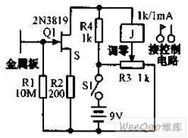
The touch plate relay circuit is as shown in the figure, when the finger touches the 2 inches sheetmetal, the induction AC signal makes the MOSFET drain current to 1.7mA, the relay gets the power to close, if you connect the capacitor to the relay coil in parallel, you can delay the release.
(View)
View full Circuit Diagram | Comments | Reading(940)
Simple delay lamp circuit (2)
Published:2011/6/27 22:11:00 Author:Ecco | Keyword: Simple , delay lamp

View full Circuit Diagram | Comments | Reading(774)
Simple delay lamp circuit (3)
Published:2011/6/27 22:11:00 Author:Ecco | Keyword: Simple , delay , lamp

View full Circuit Diagram | Comments | Reading(641)
Simple light-operated street lamp circuit diagram(1)
Published:2011/6/27 21:19:00 Author:Ecco | Keyword: Simple , light-operated , street lamp
The chart shows the simple light-operated street lamp circuit which is easy to make, as long as the advent of night, lamps will be automatically lit and turned off in the daytime. The circuit has a soft start function, when night falls, the natural light is gradually weak, so the photosensitive resistor RL is larger gradually, and VT gate level is gradually increased. Therefore, the on and off atate of thyristor is a stage of micro-conduction and conduction-weak, so the light E has a soft-start process of been gradually brighten.
(View)
View full Circuit Diagram | Comments | Reading(1985)
Light control circuit diagram
Published:2011/6/27 4:16:00 Author:Ecco | Keyword: Light control
View full Circuit Diagram | Comments | Reading(1181)
2 ~ 33MHz band-pass filter circuit formed by low-pass and high pass filter in series
Published:2011/6/20 6:31:00 Author:John | Keyword: band-pass filter, high pass filter

The filter shown in the figure is not so beautiful than the above on but with equally effectiveness. This approach is to combine the low-pass part and high pass part in series. The input section is the AM-BCB filter applied above, while the output section is the same design of a 33MHz low-pass filter. (View)
View full Circuit Diagram | Comments | Reading(818)
Simple light-operated street lamp circuit diagram(2)
Published:2011/6/27 21:24:00 Author:Ecco | Keyword: Simple, light-operated , street lamp

The chart shows the simple light-operated street lamp circuit, which is simple, easy to use. The current flowing lamp is the full-wave AC current, so the lamp light is in a normal state. Its brightness is much more than half-voltage power supply, and electronic circuit and light bulbs use two-wire connection to simplify installation.
(View)
View full Circuit Diagram | Comments | Reading(804)
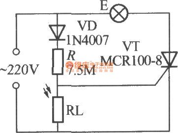
Simple light-operated street lamp circuit diagram(3)
Published:2011/6/27 21:57:00 Author:Ecco | Keyword: Simple , light-operated , street lamp

VDP is the photodiode and it has low resistance in the day, and resistance ≤ 1kΩ, then transistor VT2 is turned off, then thyristor VT1 is in the off-state as the gate has no trigger current, and E can not be lit. In the night, VL shows a high resistance as no light exposure, and the resistance ≥ 100kΩ, then VT2 is turned on, and the emitter can output positive trigger current whcih is flowing through the gate of VT1, the opening of VT1, then E is lit. Adjusting RP can turn on EL when the lighting circuit needs to be lit. The regulator VS is set in the circuit to make it work more stable and reliable.
(View)
View full Circuit Diagram | Comments | Reading(1571)
Simple light-operated street lamp circuit diagram(4)
Published:2011/6/27 22:06:00 Author:Ecco | Keyword: Simple , light-operated , street lamp

The chart shows the simple light-operated street lamp circuit which is made by two-way thyristor, and it also uses two-wire connection, so installation is relatively simple. During the day, photo-resistor RL the low resistance due to exposure of natural light. The circuit has a soft-start process, which can help to extend the lamp life. Increasing or decreasing the value of R1 can change the sensitivity of light control circuit, but generally it does not have to adjust. VDH can use the bi-directional trigger diode with the turning voltage in 20 ~ 40V, such as 2CTS, DB3 types.
(View)
View full Circuit Diagram | Comments | Reading(1483)
Simple light-operated street lamp circuit diagram(5)
Published:2011/6/27 22:08:00 Author:Ecco | Keyword: Simple , light-operated , street lamp

The chart shows the simple light-operated street lamp circuit which is made by two-way thyristor, and it consists of three major componentsof thyristor major loop, light control switches and power circuit.
(View)
View full Circuit Diagram | Comments | Reading(853)
2 ~ 33MHz band-pass filter circuit
Published:2011/6/20 6:26:00 Author:John | Keyword: band-pass filter

Band-pass filter is to pass all frequencies which are higher than for those low-end cutoff frequency and are lower than the high cutoff frequency. The designed band in the shown figure is from ZMHz to 33MHz. therefore, it covers the entire HF shortwave band to eliminate interference from the LF and MWAM band and VHF television broadcasting stations. It should be noted that each part is within its own respective shield. Such is quite a good design for any multiply-section filter because it prevents the mutual influences within the components (especially the coil).
(View)
View full Circuit Diagram | Comments | Reading(1245)
Band stop filter / notch filter resonant circuit
Published:2011/6/20 6:20:00 Author:John | Keyword: Band stop filter, notch filter

Band stop filter is a kind of band-stop filter with high Q value (referring to the narrow bandwidth). They are designed to filter out a single frequency signal. More precisely, they are to filter out a narrow-band signal around a center frequency.
Band stop filter is used to eliminate interference of a single frequency. For example, when you are close to a FM radio station, you will find that the signals cover a large area in this band or appear on a number of frequency points in this band.
(View)
View full Circuit Diagram | Comments | Reading(1904)
Simple light-operated street lamp circuit diagram(7)
Published:2011/6/27 20:42:00 Author:Ecco | Keyword: Simple , light-operated , street lamp

The chart shows the automatic light-operated street lamp circuit with good performance, and it has high sensitivity, stable performance and good robustness. In the figure, R1, C1 form the interference pulse absorption circuit to prevent short-term light exposure at night or circuit malfunction caused by leaves, flying paper and short-term shelter and other factors in the day. T uses 220V/25V, 25VA high-quality power transformer,which requires no-heating for a long time. K can use JQX-13F, DC24V power electromagnetic relay with the contact capacity in AC220V, 15A.
(View)
View full Circuit Diagram | Comments | Reading(597)
Qualcomm AM band suppression filter circuit
Published:2011/6/20 6:15:00 Author:John | Keyword: suppression filter, AM band

Many shortwave receivers would be adversely affected in front of the critical frequency, even if the rest parts of the receiver work well. For example, the sensitivity and intermediate frequency (IF) performance may be a good, but the third-order non-linear intercept point, dynamic range, intermediation performance are not up to the standard. If such happens, the receiver may be overloaded or without enough sensitivity or not able to obtain the desired signal. A basic source for front-end overload is the local AM band signals. Signals nearby the radio are rather strong. (View)
View full Circuit Diagram | Comments | Reading(1027)
Simple gradually dark/light switch circuit (1)
Published:2011/6/27 22:22:00 Author:Ecco | Keyword: Simple , gradually dark, light, switch circuit

Usually the switch S is in the open state, and transistors VT1, VT2 are turned off, then light E is off. Just close the S, 220V AC is rectified by the VD1 ~ VD4 and becomes pulsating DC output, which will charge for capacitor C through switch S and resistor R, so the voltage across C is gradually increased. Thus VT1 can obtain the base bias from low to high by R2, then VT1, VT2 enter the enlarged state gradually from deadline state, finally into a fully on state, so the light E is brighten from dark gradually.
(View)
View full Circuit Diagram | Comments | Reading(872)
AM BCB (500 ~ 2000kHz) band-pass filter circuit
Published:2011/6/20 6:08:00 Author:John | Keyword: band-pass filter

The picture shows the band-pass filter for AM broadcast band. This type of filter can be used for antenna and AM broadcast-band receiver’s antenna input terminal. It can reduce possible band signals which may interfere receiver or reduce the effects of the receiver. This filter is composed of a 2000kHz low-pass filter and a 500kHz high-pass filter in series.
(View)
View full Circuit Diagram | Comments | Reading(3147)
| Pages:1680/2234 At 2016611662166316641665166616671668166916701671167216731674167516761677167816791680Under 20 |
Circuit Categories
power supply circuit
Amplifier Circuit
Basic Circuit
LED and Light Circuit
Sensor Circuit
Signal Processing
Electrical Equipment Circuit
Control Circuit
Remote Control Circuit
A/D-D/A Converter Circuit
Audio Circuit
Measuring and Test Circuit
Communication Circuit
Computer-Related Circuit
555 Circuit
Automotive Circuit
Repairing Circuit