
Circuit Diagram
Index 1670
The odd frequency divider counter of the symmetric output waveform(SN7474 and SN74163)
Published:2011/6/26 20:25:00 Author:Borg | Keyword: frequency divider, symmetric output waveform
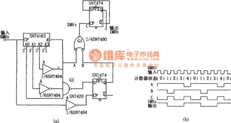
In the figure is the odd frequency divider counter of the symmetric output waveform(SN7474 and SN74163). Sometimes, we need to divide the clock pulse at odd times, and the duty cycle is 50%. Under this condition, an ordinary counter just needs 2 triggers and several gate circuits, see as the figure. When the 20-bit of the counter is logic 1 , meanwhile,21 and 22-bit output 0 logic, the B point is logic 0 ; when the 22-bit of the counter is 1 , the logic of A is 0 . (View)
View full Circuit Diagram | Comments | Reading(1765)
The frequency divider (CD4040) of converting the 50Hz or 60Hz into their 1/60
Published:2011/6/26 20:15:00 Author:Borg | Keyword: frequency divider, 50Hz, 60Hz
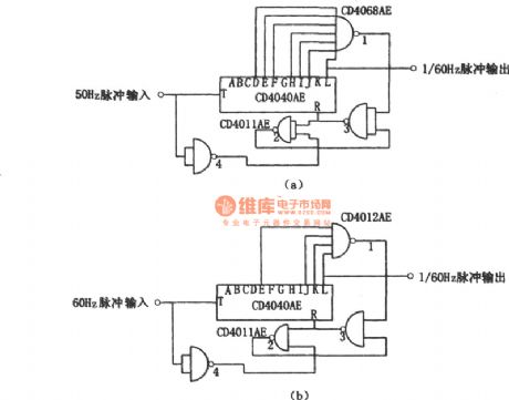
In the figure is the frequency divider (CD4040) of converting the 50Hz or 60Hz into their 1/60. As CMOS is integrated, and it's multi-stage, so a CMOS integrated circuit can divede the 50Hz or 60Hz signals, and they are output at the period of 1min. This circuit is installed with a 12-stage counter CD4040AE, which can switch the 50Hz input pulse signal into the output pulse whose period is 1min, the dividing coefficient is 50×60=3000. The way to change the decimal 3000 into to binary is to divide 3000 by 2 continuously, all the even number is marked as 0 .
(View)
View full Circuit Diagram | Comments | Reading(3221)
Non-two-wire system sound and light control stairs delay switch circuit(1)
Published:2011/6/27 22:50:00 Author:Ecco | Keyword: Non-two-wire , system , sound , light , control, stairs delay switch
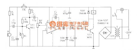
The use of two-wire connection, that is ,the switch only connects two external outgoing lines, so the installation is very convenient. Non-two-wire system sound and light control stairs delay switch circuit is shown as the chart, although the installation has too much trouble, the work has very good reliability, and in some cases it is still quite useful. In the Figure, K can use JZC-22F, DC12V small medium power relay, and T uses 220V/12V, 5VA small, high quality power transformer and other components are required as shown.
(View)
View full Circuit Diagram | Comments | Reading(509)
The digital frequency divider (SN7490, SN7442 and SN74150)
Published:2011/6/26 20:35:00 Author:Borg | Keyword: digital frequency divider
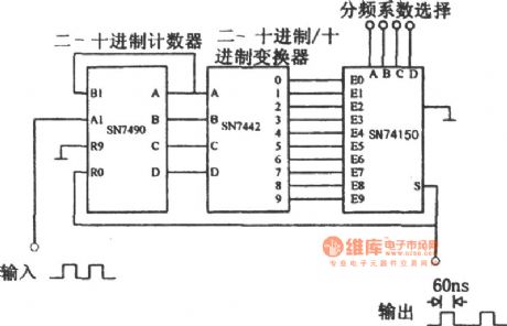
In the figure is the digital frequency divider, which consists of 3 integrated circuits, and its dividing coefficient ranges from 1 to 9. The counter SN7490 outputs the binary-coded decimal numbers which are sent to the decoder SN7442, and the decoder outputs decimal numbers. The dividing coefficient is decided by the selector SN 74150. The output of the data selector is fed back to the reset input terminal of SN7490, i.e a pulse is output once a counting period is over, the pulse is resetting the counter SN7490 at the same time. The width of the pulse is 60ns, which is decided by the delayed transmitting time. (View)
View full Circuit Diagram | Comments | Reading(3533)
Non-two-wire system sound and light control stairs delay switch circuit(2)
Published:2011/6/27 22:53:00 Author:Ecco | Keyword: Non-two-wire , system , sound , light , control , stairs delay switch
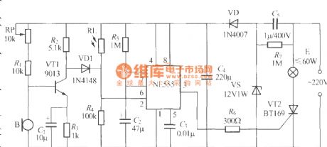
The chart shows the non-two-wire system sound and light control stairs delay switch circuit composed of NE555 time-base circuit, and it has the characteristics of precise delay time and so on.
(View)
View full Circuit Diagram | Comments | Reading(505)
Non-two-wire system sound and light control stairs delay switch circuit(3)
Published:2011/6/28 1:15:00 Author:Ecco | Keyword: Non-two-wire , system , sound , light , control, stairs delay switch
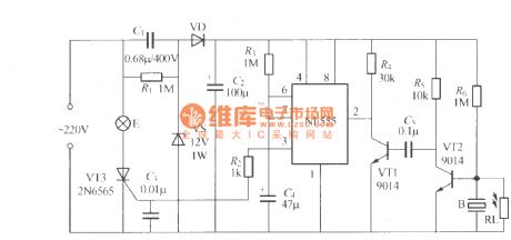
The chart shows the non-two-wire system sound and light control stairs delay switch circuit composed of NE555 time-base circuit, and it has the characteristics of good effect and simple circuit.
(View)
View full Circuit Diagram | Comments | Reading(508)
The 1.25v~37v adjustable power supply composed of LM317
Published:2011/6/15 22:54:00 Author:Borg | Keyword: adjustable power supply

In the figure is the 1.25v~37v adjustable power supply circuit, which is a typical application cirucit of the adjustable 3-terminal stabilizer, it characterizes good functions, stable working, small size and simple installation, its maximum output current is 1.5A and its output voltage ranges from 1.25V to 37V. The circuit is suitable for experiment power supply.In the figure, C3 is used to filter to wave on RP, so that the stability of the power supply voltage is raised. Due to some reasons, when the output terminal and input terminal of LM317 are short, C2 will break the chip by releasing power in LM317, and VD6 can provide a discharging circuit for C2. (View)
View full Circuit Diagram | Comments | Reading(1101)
Non-two-wire system sound and light control stairs delay switch circuit(4)
Published:2011/6/28 1:21:00 Author:Ecco | Keyword: Non-two-wire , system , sound , light , control , stairs delay switch
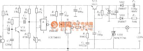
The chart shows the non-two-wire system sound and light control stairs delay switch circuit composed of CD4011 digital IC and discrete components, and the circuit is characterized by strong anti-interference performance, stable and reliable work.
(View)
View full Circuit Diagram | Comments | Reading(564)
Non-two-wire system sound and light control stairs delay switch circuit(5)
Published:2011/6/28 1:25:00 Author:Ecco | Keyword: Non-two-wire , system , sound , light , control, stairs delay switch
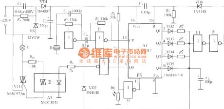
The chart shows the non-two-wire system sound and light control stairs delay switch circuit composed of CD4017, CD4069 and thyristor-type coupler, which is characterized by clapping number to choose different delay time.
(View)
View full Circuit Diagram | Comments | Reading(1206)
Nickel cadmium battery automatical charger, discharger circuit diagram
Published:2011/6/28 2:31:00 Author:Ecco | Keyword: Nickel cadmium , battery , automatical, charger, discharger

This circuit can use two nickel-cadmium batteries, when it is charged to 3V or discharge to 1-34V, it automatically disconnect the charging or discharging circuit to effectively prevent the overcharge or over discharge. The voltage rectified by D1, D2 to supply the battery, and the voltage rectified by D3 ~ D6 to supply voltage comparing and controlling circuit. TL082 constitutes a comparison circuit, and the pin 2 of LM317 provides a constant output voltage as a reference point, and the voltage of pin 3 is from the battery. Controlling the relay can control charge or discharge circuit.
(View)
View full Circuit Diagram | Comments | Reading(1277)
The +5V stable power supply with functions of current expanding and over-voltage protection(7805)
Published:2011/6/14 23:57:00 Author:Borg | Keyword: power supply, current expanding, over-voltage protection

View full Circuit Diagram | Comments | Reading(978)
The serial port dynamic state scanning display circuit
Published:2011/6/26 22:33:00 Author:Borg | Keyword: serial port, dynamic state, display


(View)
View full Circuit Diagram | Comments | Reading(741)
The electronic energy saving lamp maintenance circuit diagram
Published:2011/6/28 2:38:00 Author:Ecco | Keyword: electronic , energy saving lamp , maintenance


The saving lamp circuit has the glass cover type and exposed type. Glass cover types have three series of spherical, cylindrical ball, processing type, etc. , the first two series have completely four types of transparent, carving, engraving and white color. It has the advantages of beautiful appearance, easy installation, anti-collision, etc.; exposed type has the types of H, UH-based, 3U, 4U-based, 2D and screw type. They also can be divided by the color of light, which can be divided into red, green, blue, yellow (color temperature is 2700K, and it belons to warm light which is similar to incandescent light color), white (color temperature is 6400K, is a cool light which similar to fluorescent light color); the lamps with color temperature in 5000K has no irritation to the eyes as the light color close to natural light.
(View)
View full Circuit Diagram | Comments | Reading(4927)
The Doppler security alarm circuit
Published:2011/6/27 20:32:00 Author:Borg | Keyword: Doppler, security alarm
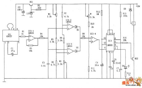
In the figure is the Doppler security alarm circuit. This circuit consists of the voltage comparator, Doppler effect sensor integrated circuit, trigger single steady and time delay circuit and so on. The chip IC3 is made of the dual time-based circuit 556, half of which composes the single steady trigger with R13 AND C7, the other half composes the single steady time delay circuit with R12 and C4, the delayed time is td=1.1R12C4, the delayed time according to the figured parameter is about 10s, which makes the master have enough time to leave the spot. The chip IC2 is adopted with the 4-op-amp LM324. IC2-2 and IC2-3 compose the window comparator.
(View)
View full Circuit Diagram | Comments | Reading(969)
The wireless alarm circuit with language chip
Published:2011/6/27 20:43:00 Author:Borg | Keyword: wireless alarm circuit, language chip
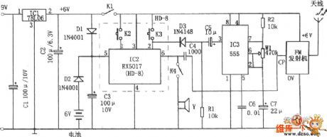
In the figure is the wireless alarm circuit with language chip. The alarm consists of the FM emitter, time-based circuit 555, regulated circuit and the language storage composed of the chip RX5017. In the figure, 555, R2, W1 and C7 compose the astable multi-resonance oscillator, whose frequency is f=l.44/(R1+Rwl)C7 which can be changed by adjusting W1. IC2 is the language chip RX5017, 3-pin is the power supply terminal, 5-pin is the maintain terminal of info storage, all of which are connected with the 6V battery by D2 to avoid power-off, 2-pin is the recording trigger terminal.
(View)
View full Circuit Diagram | Comments | Reading(736)
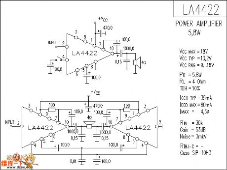
LA4422 audio IC circuit diagram
Published:2011/6/28 2:55:00 Author:Ecco | Keyword: audio IC
View full Circuit Diagram | Comments | Reading(2045)
LA4282 audio IC circuit diagram
Published:2011/6/28 2:56:00 Author:Ecco | Keyword: audio IC

View full Circuit Diagram | Comments | Reading(2707)
Infrared remote control switch circuit diagram
Published:2011/6/28 2:53:00 Author:Ecco | Keyword: Infrared , remote control , switch


Making such a remote control switch is very simple, even beginners can do it well, because this circuit is too simple, and it only requires a dozen components. The SCM is used as the processing chip, so the circuit is simple. The SCM uses PIC12F629, and the integrated remote control receiver uses TSOP1738, of course, if you do not find this type of receiver, you can use an alternative model, and the relay chooses 12V relay.
(View)
View full Circuit Diagram | Comments | Reading(2302)
Universal infrared remote control power outlet circuit diagram
Published:2011/6/28 3:02:00 Author:Ecco | Keyword: Universal, infrared , remote control , power outlet

Outlet circuit is shown in Figure 1. The circuit uses a receiver, amplification, demodulation integrated infrared receiver, and the relay trigger drive circuit uses one dual D flip-flop MC14013, and the circuit uses only one way, which is connected into a bi-stable form, and D is connected to Q, R, S are grounded. R3, C2 RC network connected to the R side has the power-on reset function to ensure the socket is in off state when the circuit gets power after power cut. Figure 2 shows the PCB map.
(View)
View full Circuit Diagram | Comments | Reading(2138)
The 8-line remote control emitter(CS901) circuit
Published:2011/6/27 20:54:00 Author:Borg | Keyword: 8-line, remote control emitter

In the figure is the 8-line remote control emitter which is composed of the CS901 module and the digital encoder SM5262 (the same with PT2262), the keys SA1~SA8 and diodes VD1~VD13 compose the 8-line matrix input circuit as the encoding input circuit of the emitter. As the 7~13 pins of SM5262 are the address/data sharing terminals, if they are regarded as the data input terminal, the circuit will have 6 data input terminals in total, when all their functions are taken as the data input, they can compose the 26=64, i.e the 64-way, remote control emitter. In the circuit, only 4 terminals of D1~D4 are put in use.
(View)
View full Circuit Diagram | Comments | Reading(3717)
| Pages:1670/2234 At 2016611662166316641665166616671668166916701671167216731674167516761677167816791680Under 20 |
Circuit Categories
power supply circuit
Amplifier Circuit
Basic Circuit
LED and Light Circuit
Sensor Circuit
Signal Processing
Electrical Equipment Circuit
Control Circuit
Remote Control Circuit
A/D-D/A Converter Circuit
Audio Circuit
Measuring and Test Circuit
Communication Circuit
Computer-Related Circuit
555 Circuit
Automotive Circuit
Repairing Circuit