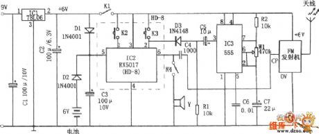
Control Circuit
The wireless alarm circuit with language chip
Published:2011/6/27 20:43:00 Author:Borg | Keyword: wireless alarm circuit, language chip | From:SeekIC

In the figure is the wireless alarm circuit with language chip. The alarm consists of the FM emitter, time-based circuit 555, regulated circuit and the language storage composed of the chip RX5017. In the figure, 555, R2, W1 and C7 compose the astable multi-resonance oscillator, whose frequency is f=l.44/(R1+Rwl)C7 which can be changed by adjusting W1. IC2 is the language chip RX5017, 3-pin is the power supply terminal, 5-pin is the maintain terminal of info storage, all of which are connected with the 6V battery by D2 to avoid power-off, 2-pin is the recording trigger terminal.
Reprinted Url Of This Article:
http://www.seekic.com/circuit_diagram/Control_Circuit/The_wireless_alarm_circuit_with_language_chip.html
Print this Page | Comments | Reading(3)

Article Categories
power supply circuit
Amplifier Circuit
Basic Circuit
LED and Light Circuit
Sensor Circuit
Signal Processing
Electrical Equipment Circuit
Control Circuit
Remote Control Circuit
A/D-D/A Converter Circuit
Audio Circuit
Measuring and Test Circuit
Communication Circuit
Computer-Related Circuit
555 Circuit
Automotive Circuit
Repairing Circuit
Code: