
Circuit Diagram
Index 1676
The stereo OTL power amplifier circuit of 6N5P valve
Published:2011/6/28 0:48:00 Author:Borg | Keyword: stereo, power amplifier, valve

The stereo OTL power amplifier circuit of 6N5P valve is shown as above.
(View)
View full Circuit Diagram | Comments | Reading(2365)
The common high-voltage multiplier circuit
Published:2011/6/28 0:49:00 Author:Borg | Keyword: high-voltage, multiplier

The common high-voltage multiplier circuit is shown as above.
(View)
View full Circuit Diagram | Comments | Reading(778)
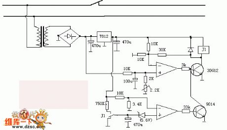
Agricultural non-tower pressurized water feeder circuit diagram 1
Published:2011/6/18 20:25:00 Author:Lucas | Keyword: Agricultural, non-tower , pressurized , water feeder

The agricultural non-tower pressurized water feeder circuit is composed of the power supply circuit and the detection control circuit, and the circuit is shown as the chart 1. Power supply circuit consists of the knife switch Q1, fuse FU, power switch S1, step-down capacitor C1, drain resistor R1, Zener diode VS, rectifier diode VD and filter capacitor C2. Detection control circuit is composed of electric contact pressure gauge Q2, resistors R2 ~ R9, capacitor C3, control switch S2, time-base integrated circuit IC, LEDs VL1, VL2, thyristor VT, AC contactor KM and thermal relay FR. R1 ~ R9 select 1/4W metal film resistors or carbon film resistors.
(View)
View full Circuit Diagram | Comments | Reading(612)
The wireless microphone circuit of MC2831
Published:2011/6/28 0:39:00 Author:Borg | Keyword: wireless microphone

The wireless microphone circuit of MC2831 is shown as above.
(View)
View full Circuit Diagram | Comments | Reading(3155)
Automatic sprinkler controller circuit diagram 7
Published:2011/6/18 22:15:00 Author:Lucas | Keyword: Automatic , sprinkler controller

The automatic sprinkler controller circuit consists of soil moisture detection sensor, Schmitt trigger, monostable flip-flop, LED display circuit and control implementation circuit, and the circuit is shown in the chart. Schmitt trigger is composed of the Dl, D2 which are inside of the four NAND gate integrated circuit IC (Dl ~ D4) and resistors R1, R2, capacitors Cl, C2, potentiometer RP1. Monostable flip-flop is composed of the D3 D4 which are inside of IC, resistors R3, R4, potentiometer RP2 and capacitor C3. LED display circuit consists of transistor V3, light-emitting diodes VLI, VL2, and resistor R5 ~ R7. Control implementation circuit consists of the resistor R8, transistors VI, V2, relay K and diode VD. (View)
View full Circuit Diagram | Comments | Reading(1228)
A self-recovery over-voltage protection circuit
Published:2011/6/28 0:22:00 Author:Borg | Keyword: self-recovery, over-voltage, protection circuit
View full Circuit Diagram | Comments | Reading(844)
Vizi saloon car brake light, backup light, wiper and scrubber circuits
Published:2011/6/28 19:16:00 Author:TaoXi | Keyword: Vizi, saloon car, brake light, backup light, wiper, scrubber
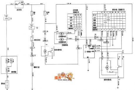
Vizi saloon car brake light, backup light, wiper and scrubber circuits are as shown in the figure:
(View)
View full Circuit Diagram | Comments | Reading(397)
Automatic sprinkler controller circuit diagram 6
Published:2011/6/18 22:04:00 Author:Lucas | Keyword: Automatic, sprinkler controller

The automatic sprinkler controller circuit is composed of the power supply circuit and humidity detection control circuit, and the circuit is shown in the chart. Power supply circuit is composed of the power transformer T, bridge rectifier UR, isolation diode VD2, zener diode VS and filter capacitors C1, C2 and so on. Humidity detection control circuit consists of the humidity sensor, the transistors V1 ~ V3, resistors R1 ~ R5, diode VDI and relay K. RI, R3 ~ R5 select l/4W carbon film resistors; R2 uses sealed variable resistor. C1 and C2 select the aluminum electrolytic capacitors with the voltage in 16V. VD1 uses the IN4007 silicon rectifier diode; VD2 uses the lN5401 silicon rectifier diode.
(View)
View full Circuit Diagram | Comments | Reading(966)
Electronic induced scorpion light circuit diagram
Published:2011/6/18 20:18:00 Author:Lucas | Keyword: Electronic, induced scorpion light

Electronic induced scorpion light circuit is composed of the transistor V, pulse transformer T2, resistor R, capacitors C1 ~ C4, light switch S2, power transformer T1, battery CB, bridge rectifier UR, power transformer T2 and the power switch S1, and the circuit is shown as the chart. T1, UR, C1, GB, and S1, S2 form power supply circuit. V, T2, R, C2 ~ C4 form the pulse oscillator circuit. R selects the 1/4W metal film resistor or carbon film resistor. C1 selects the aluminum electrolytic capacitor with the voltage in 16V ; C2 and C3 select high frequency ceramic capacitors; C4 uses the monolithic capacitor.
(View)
View full Circuit Diagram | Comments | Reading(2170)
Robot monitoring circuit
Published:2011/6/21 6:06:00 Author:Lucas | Keyword: Robot , monitoring circuit
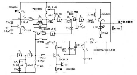
In the circuit, VT5 is the input circuit, which uses the TPSA6O3A phototransistor, and the current in VT5 can change with varying degrees of light and shade in environment. If VT5 connected the emitter resistance, the sensitivity of VT5 detecting light changes is reduced. To this, the circuit is connected the VTl transistor, and the potential of A point becomes the sum of VTl base - emitter and VD1 forward voltage drop. Usually, the current of VT5 is very low, and A point potential is almost constant. F1, F2 and VT2 and VT3, etc. constitute the motor control circuit, and Fl and F2 form the oscillator circuit.
(View)
View full Circuit Diagram | Comments | Reading(497)
The Honda-Odessey power door and rearview mirror circuit
Published:2011/6/28 20:46:00 Author:qqtang | Keyword: Honda-Odessey, power door, rearview mirror
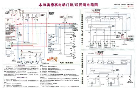
The Honda-Odessey power door and rearview mirror circuit is shown as above.
(View)
View full Circuit Diagram | Comments | Reading(395)
The voltage monitoring and resetting circuit composed of TL7705CP
Published:2011/6/28 20:44:00 Author:qqtang | Keyword: voltage monitoring, resetting circuit

View full Circuit Diagram | Comments | Reading(777)
The 110V AC-12V/8A DC switch power supply circuit
Published:2011/6/28 20:21:00 Author:qqtang | Keyword: DC, AC, switch power supply

Figure:The 110V AC-12V/8A DC switch power supply circuit (View)
View full Circuit Diagram | Comments | Reading(2430)
The Buick-Century power window, chair, auto rearview mirror circuit
Published:2011/6/28 20:15:00 Author:qqtang | Keyword: Buick-Century, window, rearview mirror circuit
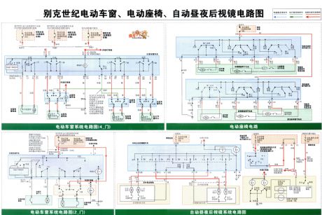
The Buick-Century power window, chair, auto rearview mirror circuit is shown in the figure.
(View)
View full Circuit Diagram | Comments | Reading(695)
Robot tracking circuit
Published:2011/6/21 5:59:00 Author:Lucas | Keyword: Robot, tracking circuit
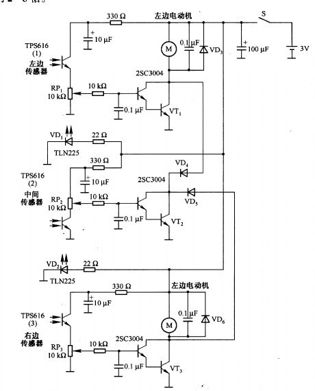
In the ircuit, TPS616 (1), TPS616 (2) and TPS616 (3) are respectively the left, middle and right light receiving sensor, which are the filter phototransistors with visible light cut-off filter. If the sensitivity of TPS616 is not enough, it can use TPS6ll. The 9OOnm peak wavelength of TPS6l1 is the same with TPS616. TLN225 is the infrared light-emitting diode with the peak wavelength in 870nm. It can also use TLNlO5 with the the peak wavelength in 950nm. Motor drive uses 2SC3004 Darlington transistor, which can also be replaced by the same type Darlington power transistor.
(View)
View full Circuit Diagram | Comments | Reading(606)
Double control light switch circuit
Published:2011/6/28 18:50:00 Author:TaoXi | Keyword: Double control, light switch

The double control switch is also called the ganged switch, it can be used in two different places such as the lower and upper stairs or the two ends of the aisle, it can independently control the turn-on or turn-off of the same light. The three connections are as shown in the figure, the S1 and S2 are the 1×2 SPDT switches, they can independently control the turn-on or turn-off of the light E. The connection of figure (b) shows that every switch has the phase line and the zero line of the power supply, so it is easy to install, but you need to pay more attention on the phase line and the zero line's short circuit when you are maintaining it.
(View)
View full Circuit Diagram | Comments | Reading(1817)
The circuit composed of AICl783
Published:2011/6/28 20:31:00 Author:qqtang | Keyword: circuit

View full Circuit Diagram | Comments | Reading(607)
The switch power supply circuit of 220v AC-5V/10A DC
Published:2011/6/28 20:30:00 Author:qqtang | Keyword: switch power supply, AC, DC

Figure:The switch power supply circuit of 220v AC-5V/10A DC (View)
View full Circuit Diagram | Comments | Reading(2031)
The typical application circuit of MAX834/835
Published:2011/6/28 20:35:00 Author:qqtang | Keyword: typical application

View full Circuit Diagram | Comments | Reading(662)
The Dongfeng-Funshion lighting system circuit
Published:2011/6/28 20:34:00 Author:qqtang | Keyword: Dongfeng-Funshion, lighting system

The Dongfeng-Funshion lighting system circuit is shown as above.
(View)
View full Circuit Diagram | Comments | Reading(640)
| Pages:1676/2234 At 2016611662166316641665166616671668166916701671167216731674167516761677167816791680Under 20 |
Circuit Categories
power supply circuit
Amplifier Circuit
Basic Circuit
LED and Light Circuit
Sensor Circuit
Signal Processing
Electrical Equipment Circuit
Control Circuit
Remote Control Circuit
A/D-D/A Converter Circuit
Audio Circuit
Measuring and Test Circuit
Communication Circuit
Computer-Related Circuit
555 Circuit
Automotive Circuit
Repairing Circuit