Basic Circuit
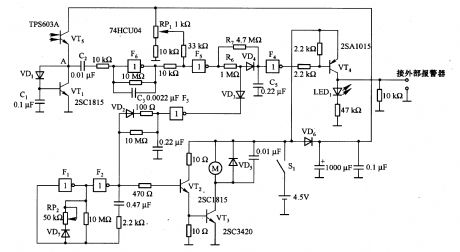
Robot monitoring circuit
Published:2011/6/21 6:06:00 Author:Lucas | Keyword: Robot , monitoring circuit | From:SeekIC

In the circuit, VT5 is the input circuit, which uses the TPSA6O3A phototransistor, and the current in VT5 can change with varying degrees of light and shade in environment. If VT5 connected the emitter resistance, the sensitivity of VT5 detecting light changes is reduced. To this, the circuit is connected the VTl transistor, and the potential of A point becomes the sum of VTl base - emitter and VD1 forward voltage drop. Usually, the current of VT5 is very low, and A point potential is almost constant. F1, F2 and VT2 and VT3, etc. constitute the motor control circuit, and Fl and F2 form the oscillator circuit.
Reprinted Url Of This Article:
http://www.seekic.com/circuit_diagram/Basic_Circuit/Robot_monitoring_circuit.html
Print this Page | Comments | Reading(3)

Article Categories
power supply circuit
Amplifier Circuit
Basic Circuit
LED and Light Circuit
Sensor Circuit
Signal Processing
Electrical Equipment Circuit
Control Circuit
Remote Control Circuit
A/D-D/A Converter Circuit
Audio Circuit
Measuring and Test Circuit
Communication Circuit
Computer-Related Circuit
555 Circuit
Automotive Circuit
Repairing Circuit
Code: