
Circuit Diagram
Index 1675
Two-way diode trigger circuit
Published:2011/6/27 8:50:00 Author:Christina | Keyword: Two-way diode, trigger circuit
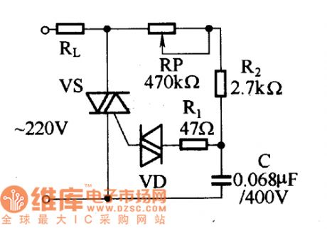
The application two-way diode trigger & two-way thyristor circuit is designed as one kind of typical and common trigger circuit, as the figure shows. In general the two-way diode is in the high impedance cut-off state. Only when you add the voltage (both positive and negative) to the two-way diode, and this voltage is higher than the breakdown voltage of the two-way diode, the two-way diode will be punctured and be conducted. The general breakdown voltage of the two-way diode is tens of volts.
When the circuit is connected with the AC city electricity, the AC city electricity will charge to the capacitance C through RL, RP, R2.
(View)
View full Circuit Diagram | Comments | Reading(935)
GuangZhou HONDA Fit saloon car engine circuit 4
Published:2011/6/19 19:03:00 Author:TaoXi | Keyword: GuangZhou, HONDA, Fit, saloon car, engine circuit
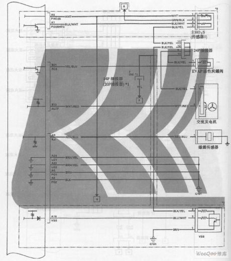
GuangZhou HONDA Fit saloon car engine circuit (View)
View full Circuit Diagram | Comments | Reading(329)
GuangZhou HONDA Fit saloon car engine circuit 3
Published:2011/6/19 19:05:00 Author:TaoXi | Keyword: GuangZhou, HONDA, Fit, saloon car, engine circuit
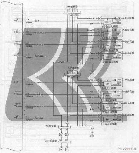
GuangZhou HONDA Fit saloon car engine circuit (View)
View full Circuit Diagram | Comments | Reading(378)
Irrigation motor automatic protector circuit diagram 1
Published:2011/6/14 4:15:00 Author:Lucas | Keyword: Irrigation motor, automatic protector
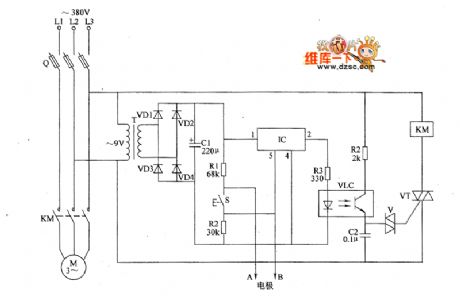
The irrigation motor automatic protector circuit is composed of the power supply circuit and the detection / protection control circuit, and the circuit is shown as the figure. Power supply circuit is composed of the power transformer T, rectifier diodes VD1 ~ VD4 and filter capacitor C1. Detection / protection circuit is composed of the detection electrodes A, B, Start button S, resistors R1 ~ R4, capacitor C2, optocoupler VLC, bi-directional trigger diode V, thyristor VT, electronic switch IC IC and AC contactor KM. AC 380V voltage is bucked by T, rectified by VDI ~ VD4 and filtered by C1 to provide 9V DC voltage for the electronic switch IC IC. RI ~ RZI select l/4W metal film resistors.
(View)
View full Circuit Diagram | Comments | Reading(1101)
GuangZhou HONDA Fit saloon car engine circuit 6
Published:2011/6/19 19:02:00 Author:TaoXi | Keyword: GuangZhou, HONDA, Fit, saloon car, engine circuit
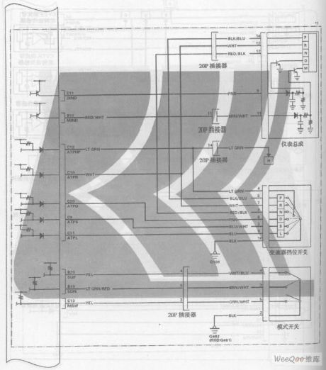
GuangZhou HONDA Fit saloon car engine circuit (View)
View full Circuit Diagram | Comments | Reading(351)
GuangZhou HONDA Fit saloon car engine circuit 2
Published:2011/6/19 19:06:00 Author:TaoXi | Keyword: GuangZhou, HONDA, Fit, saloon car, engine circuit
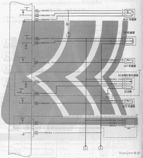
GuangZhou HONDA Fit saloon car engine circuit (View)
View full Circuit Diagram | Comments | Reading(406)
GuangZhou HONDA Fit saloon car engine circuit 7
Published:2011/6/19 19:01:00 Author:TaoXi | Keyword: GuangZhou, HONDA, Fit, saloon car, engine circuit
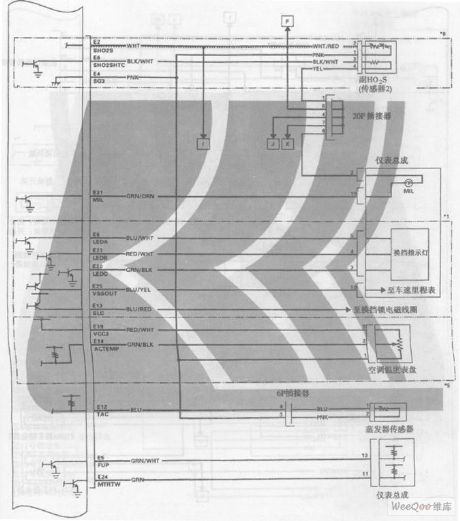
GuangZhou HONDA Fit saloon car engine circuit (View)
View full Circuit Diagram | Comments | Reading(346)
Agricultural irrigation line burglar alarm circuit diagram 2
Published:2011/6/16 3:47:00 Author:Lucas | Keyword: Agricultural, irrigation line , burglar alarm

The agricultural irrigation line burglar alarm circuit is composed of the detection circuit, LED indicator circuit and sound alarm circuit, and the circuit is shown as the chart. Detection circuit is composed of the test buttons S1 ~ S3, resistors RI ~ R3, capacitors C1 ~ C12 and diodes VD1 ~ VD3, VD7, VD9, VD13 ~ VD15. LED indicator circuit consists of resistors R4 ~ R6, light-emitting diodes VL1 ~ VL3, transistors VI ~ V6 and diodes VD4 ~ VD6, VD10 ~ VD12, VD16 ~ VD18. Sound alarm circuit is composed of the audio integrated circuit IC, capacitors C5 ~ C7, transistor V7 and speaker BL. R1, R3 and R5 select 1/2W metal film resistors.
(View)
View full Circuit Diagram | Comments | Reading(857)
Agricultural irrigation line burglar alarm circuit diagram 1
Published:2011/6/16 3:42:00 Author:Lucas | Keyword: Agricultural , irrigation line, burglar alarm

The agricultural irrigation line burglar alarm circuit is composed of the detection circuit and sound alarm circuit, and the circuit is shown as the chart. Detection circuit consists of resistors R1 ~ R12, LEDs VL1 ~ VL3, transistors VI ~ V6. Sound alarm circuit is composed of the diodes VD1 ~ VD3, transistors V7, V8, capacitors C1 ~ C3, resistor R13, audio integrated circuit IC and speaker BL. R1 ~ R13 select 1/4W metal film resistors or carbon film resistors. C1 and C4 select the aluminum electrolytic capacitors with the voltage in 10V; C2 uses the monolithic capacitor or polyester capacitor.
(View)
View full Circuit Diagram | Comments | Reading(666)
Agricultural irrigation controller circuit diagram 2
Published:2011/6/16 3:36:00 Author:Lucas | Keyword: Agricultural , irrigation controller

The agricultural irrigation controller circuit is composed of the power circuit, water level detection control circuit and control implementation circuit, and the circuit is shown as the chart. The power supply circuit is composed of the step-down capacitor C1, discharge resistor RI, rectifier diodes VD1, VD2, voltage regulator diode VS and filter capacitor C2. Water level detection control circuit is composed of the water level detection electrodes a, b, resistors R2 ~ R4, electronic integrated circuit and opto-coupler switch VLC. R1 selects 1/2W metal film resistor; R2 ~ R5 select l/4W metal film resistors or carbon film resistors.
(View)
View full Circuit Diagram | Comments | Reading(1249)
Intermittent power controller circuit diagram 7
Published:2011/6/16 4:07:00 Author:Lucas | Keyword: Intermittent , power controller

The intermittent power control circuit is composed of the power supply circuit, timer and control implementation circuit, and the circuit is shown as the Figure. The power supply circuit is composed of the step-down capacitor C2, discharge resistor R3, bridge rectifier UR, voltage regulator diode VS, current limiting resistors R4, R5, filter capacitor C3 and power indicator light-emitting diode VL. The timer circuit consists of counts / divider integrated circuit IC and resistors R1, R2, R6, capacitor C1 and diodes VD2 ~ VD4 . In the circuit, the R1, R2, C1 and the internal IC circuit form the clock oscillator circuit.
(View)
View full Circuit Diagram | Comments | Reading(429)
Intermittent power controller circuit diagram 6
Published:2011/6/16 4:04:00 Author:Lucas | Keyword: Intermittent , power controller

The intermittent power control circuit is composed of the power supply circuit and timing control circuit, and the circuit is shown as the Figure. The power supply circuit is composed of the step-down capacitor C1, resistors R1, R5, rectifier diodes VD1 ~ VD4, voltage regulator diode VS, power indicator LED VL1 and filter capacitor C2. Timing control circuit consists of the time-base integrated circuit IC, resistors R2 ~ R4, capacitors C3, C4, potentiometers RP1, RP2, diodes VD5, VD6, light-emitting diode VL2 and relay K. R2 ~ R5 use 1/4W carbon film resistors or metal film resistors.
(View)
View full Circuit Diagram | Comments | Reading(477)
Drainage and irrigation station centralized controller circuit diagram 2
Published:2011/6/18 21:14:00 Author:Lucas | Keyword: Drainage , irrigation , station, centralized controller

The drainage and irrigation station centralized controller circuit consists of the motor M, knife switch Q, fuse FU, AC contactors KMI ~ KM3, time relay KT, intermediate relay KA, thermal relay KR, control buttons S1, S2, signal line indicator Light HL, transformer T and buzzer HA etc., and the circuit is shown in the chart. S2 and HL, T, HA form the sound and light alarm circuit which is installed in the control room , and it connects with other irrigation and drainage stations through the signal lines a ~ n, and it can remote centralized control other pump motors by S2. KA chooses the JZC-22 AC relay. KT selects the JSD-8F time relay.
(View)
View full Circuit Diagram | Comments | Reading(506)
Drainage and irrigation station centralized controller circuit diagram 1
Published:2011/6/18 21:21:00 Author:Lucas | Keyword: Drainage, irrigation, station, centralized controller

The drainage and irrigation station centralized controller circuit consists of the knife switch Q, fuse FU, start buttons S1, S3, stop buttons S2, S4, intermediate relay KA, AC contactor KM, thermal relay KR, fluorescent starter Κ, resistors RI, R2 and light HL, and the circuit is shown in the chart. S1, R1, S2, and HL form the control and instruction circuit which is installed in the control room, and each irrigation station has a signal line connected to the circuit. RI and R2 select the 300 ~ 1000Ω, 2 ~ 3W wire wound variable resistors. S1 and S3 use 380V, 5A press-pressure making buttons; S2 and S4 use 380V, 5A press-pressure moving off buttons.
(View)
View full Circuit Diagram | Comments | Reading(549)
Agricultural non-tower pressurized water feeder circuit diagram 4
Published:2011/6/18 20:43:00 Author:Lucas | Keyword: Agricultural, non-tower, pressurized, water feeder

The agricultural non-tower pressurized water feeder circuit is composed of the power supply circuit and pressure detection control circuit, and the circuit is shown in Figure 1. Power supply circuit is composed of the fuse FU2, knife switch Q2, power transformer T, rectifier diode VD and filter capacitor C. Pressure detection control circuit consists of the electric contact pressure gauge Q3, relay Ka, intermediate relays KA1, KA2, AC contactor KM, thermal relay ER, control buttons S1, S2 and knife switch Q1 and so on. C selects the aluminum electrolytic capacitor with the voltage in 16V. VD chooses 1 N400 1 or 1 N4007 silicon rectifier diode. K1 and K2 select JRX-13F 9V DC relays.
(View)
View full Circuit Diagram | Comments | Reading(721)
GuangZhou HONDA Fit saloon car engine circuit 1
Published:2011/6/19 19:06:00 Author:TaoXi | Keyword: GuangZhou, HONDA, Fit, saloon car, engine circuit
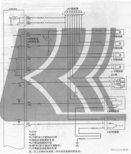
GuangZhou HONDA Fit saloon car engine circuit (View)
View full Circuit Diagram | Comments | Reading(352)
Automatic sprinkler controller circuit diagram 8
Published:2011/6/18 22:21:00 Author:Lucas | Keyword: Automatic , sprinkler controller

The automatic sprinkler controller circuit consists of the power switch Q, control button S, AC contactor KM, relays KT1, KT2, and the circuit is shown in the chart. KT1 and KT2 select the JS14S time relay. KM uses 220Y, 10A AC contactor, such as CDC10 series. KT1 gets power and works after KM1-2 closing. When the delay time set by KT1 arrives, the normally closed contacts disconnect in the delay time, then KM loses power and releases, and M stops working. At the same time, the normally closed contacts of KM are connected, then KT2 will begin to work. The above process taking place in a cycle can realize automatically timing sprinkler.
(View)
View full Circuit Diagram | Comments | Reading(617)
Agricultural non-tower pressurized water feeder circuit diagram 3
Published:2011/6/18 20:37:00 Author:Lucas | Keyword: Agricultural, non-tower, pressurized , water feeder

The agricultural non-tower pressurized water feeder circuit is composed of the power supply circuit, pressure detection circuit, control circuit and indication circuit, and the circuit is shown in Figure 1. Power supply circuit is composed of the knife switch Q1, fuses FU1, FU2, power switch S1, power transformer T, bridge rectifier UR and filter capacitor C. Pressure detection circuit consists of the electric contact pressure gauge Q2, resistors R4 ~ R7, the normally closed relay contacts K3 of relay K and transistor V. Control circuit consists of the electronic switch IC IC, diodes VD1, VD2, resistor R3, relay K, AC contactor KM, thermal relay ER, control button S2, manual / automatic control switch S3.
(View)
View full Circuit Diagram | Comments | Reading(1240)
Agricultural non-tower pressurized water feeder circuit diagram 2
Published:2011/6/18 20:32:00 Author:Lucas | Keyword: Agricultural , non-tower, pressurized , water feeder

The agricultural non-tower pressurized water feeder circuit is composed of the knife switch Q1, fuse FU, relay KA, AC contactor KM, thermal relay ER, alarm HA, lights HL1, HL2, and the control contacts of pump outlet pressure gauge Q2, the control contacts of tank water level detection pressure gauge 03, and the circuit is shown as the chart 1. When people use water, the water level inside the tank will decrease down, and when the pressure below the set maximum pressure value, the moving contact of tank water level detection pressure gauge 03 and the upper contact are open, so KA releases, HL2 turns off. HL1 and HL2 use 220V power indicator lights.
(View)
View full Circuit Diagram | Comments | Reading(1028)
The OTL power amplifier power supply current circuit
Published:2011/6/28 0:38:00 Author:Borg | Keyword: OTL, power amplifier, power supply

The OTL power amplifier power supply current circuit is shown as above.
(View)
View full Circuit Diagram | Comments | Reading(915)
| Pages:1675/2234 At 2016611662166316641665166616671668166916701671167216731674167516761677167816791680Under 20 |
Circuit Categories
power supply circuit
Amplifier Circuit
Basic Circuit
LED and Light Circuit
Sensor Circuit
Signal Processing
Electrical Equipment Circuit
Control Circuit
Remote Control Circuit
A/D-D/A Converter Circuit
Audio Circuit
Measuring and Test Circuit
Communication Circuit
Computer-Related Circuit
555 Circuit
Automotive Circuit
Repairing Circuit