Circuit Diagram
Index 1662
Computer Mainboard Circuit 440LX_24
Published:2011/6/24 2:41:00 Author: | Keyword: Computer Mainboard, 440LX_24
View full Circuit Diagram | Comments | Reading(477)
Computer Mainboard Circuit 440LX_23
Published:2011/6/24 2:42:00 Author: | Keyword: Computer Mainboard, 440LX_23
View full Circuit Diagram | Comments | Reading(500)
Computer Mainboard Circuit 440LX_22
Published:2011/6/24 2:44:00 Author: | Keyword: Computer Mainboard, 440LX_22
View full Circuit Diagram | Comments | Reading(498)
Computer Mainboard Circuit 440LX_21
Published:2011/6/24 2:46:00 Author: | Keyword: Computer Mainboard, 440LX_21
View full Circuit Diagram | Comments | Reading(479)
Computer Mainboard Circuit 440LX_20
Published:2011/6/24 2:46:00 Author: | Keyword: Computer Mainboard, 440LX_20
View full Circuit Diagram | Comments | Reading(435)
The multi-function dimmer circuit of special integrated circuits
Published:2011/6/29 0:50:00 Author:Seven | Keyword: multi-function, integrated circuits

In the figure is the multi-function dimmer circuit of HT7760 special integrated circuits, which has four different dimming functions of stepless dimming, step dimming, lights-out delay and circling auto lights-out. B can be a common voltage pottery chip, other parameters are shown in the figure, which have no special regulation.
(View)
View full Circuit Diagram | Comments | Reading(537)
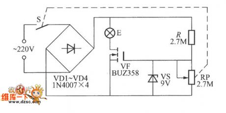
The simple V-MOSFET dimming lamp circuit
Published:2011/6/29 0:43:00 Author:Seven | Keyword: dimming lamp, V-MOSFET

The simple V-MOSFET dimming lamp circuit is shown in the circuit, which harnesses the features of V-MOSFET that its impedance is high and controls the bulb current by adjusting the bias voltage of the V-MOS pipe grid, so that the brightness of the bulb is changed. The power of E is not higher than 60W.
(View)
View full Circuit Diagram | Comments | Reading(1146)
The 811 transistor power amplifier circuit
Published:2011/6/29 4:53:00 Author:Seven | Keyword: transistor, power amplifier

The 811 transistor power amplifier circuit is shown as above.
(View)
View full Circuit Diagram | Comments | Reading(2571)
The dual key FET dimmer circuit
Published:2011/6/29 5:10:00 Author:Seven | Keyword: dual key, FET dimmer

The dual key FET dimmer circuit is shown in the figure, which adopts two light touch switches to regulate the brightness, one of them is to raise the brightness, the other is to reduce to brightness. It is easy to use and its outline is pretty.
(View)
View full Circuit Diagram | Comments | Reading(1047)
The 811A push-pull 30W power amplifier circuit
Published:2011/6/29 5:25:00 Author:Seven | Keyword: push-pull, power amplifier

The 811A push-pull 30W power amplifier circuitis shown as above.
(View)
View full Circuit Diagram | Comments | Reading(6231)
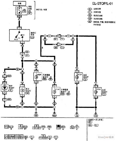
Nissan A32-EL brake lamp circuit
Published:2011/6/22 10:00:00 Author:Nancy | Keyword: Nissan, brake lamp
View full Circuit Diagram | Comments | Reading(536)
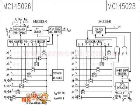
The MC145028 circuit
Published:2011/6/29 5:22:00 Author:Seven | Keyword: circuit
View full Circuit Diagram | Comments | Reading(775)
The single-way thyristor dimmer circuit triggered by single knot transistor
Published:2011/6/29 21:02:00 Author:Seven | Keyword: thyristor dimmer, single knot transistor


1.To increase the stability of the bulb, we can adopt the single-knot transistor trigger circuit in the following figure.
2.See as the figured circuit, VT1 can be 3CT1 or MCR100-8 single-way transistor.
(View)
View full Circuit Diagram | Comments | Reading(2462)
The supreme TA-292C gallstone mixing rear stage power supply circuit
Published:2011/6/29 5:42:00 Author:Seven | Keyword: gallstone, rear stage, power supply

The supreme TA-292C gallstone mixing rear stage power supply circuit is shown above.
The gallstone mixing power amplifier of beautiful sound (View)
View full Circuit Diagram | Comments | Reading(1338)
The pulse width speed regultating motor circuit
Published:2011/6/29 5:37:00 Author:Seven | Keyword: pulse width, speed regultating motor
View full Circuit Diagram | Comments | Reading(462)
The 100W power supply circuit
Published:2011/6/29 5:44:00 Author:Seven | Keyword: power supply

The 100W power supply circuit driven by TDA7250 is shown as above.
(View)
View full Circuit Diagram | Comments | Reading(1332)
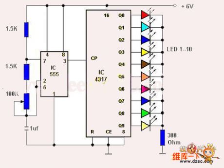
The 10-line chasing type flash circuit
Published:2011/6/29 5:46:00 Author:Seven | Keyword: chasing type
View full Circuit Diagram | Comments | Reading(466)
FSK/ASK 433MHz Emitter Circuit Diagram
Published:2011/6/19 5:15:00 Author:Vicky | Keyword: FSK/ASK 433MHz Emitter

TH72015 applied circuit
TH72015 is a FSK/ASK emitter specially designed for application for European 433 MHz ISM frequency range, which reaches EN 300 220 wireless communication standard. It is available for application in keyless entering system, remote control/remote-measuring system , data communication system and security system etc.
Main technical features are as follows:
·Work frequency: 380~450 MHz;
·Singal-ended RF output;
·FSK modulation rate: DC~40 Kb/s;
·ASK modulation rate up to 40 Kb/s;
·Voltage of power supply: l.9~5.5 V;
·Work current: 3.5~10.7 mA, stand-by current: 0.1μA;
·Output power: -12~+8.5 dBm.
(View)
View full Circuit Diagram | Comments | Reading(1321)
The simplest dual-way thyristor dimmer circuit
Published:2011/6/29 5:35:00 Author:Seven | Keyword: dual-way thyristor, dimmer circuit

In the figure is the simplest dual-way thyristor dimmer circuit, the feature of the dual-way thyristor is that whether the AC is in its positive or passive half circle, just add a proper trigger pulse or control circuit on its control pole, the thyristor will be passable, and the conducting time is relative to the pulse width or gate current. The brightness of bulb E can be changed by adjusting RP.
(View)
View full Circuit Diagram | Comments | Reading(824)
ASK 433MHz Emitter Circuit Diagram
Published:2011/6/19 5:17:00 Author:Vicky | Keyword: ASK 433MHz Emitter

TH72012 applied circuit
TH72012 is monolithic emitter chip which reaches standard of EN 300 220 and the analogs. It is available for keyless entering system, remote control/ remote measuring system, data communication system and security system etc.
Main technical features are as follows;:
·Completely integrated and stable PLL;
·Work frequency: 380~450 MHz;
·Single-ended RF output;
·ASK modulation mode;
·ASK modulation rate up to 40 Kb/s;
·Voltage of power supply: l.9~5.5 V;
·Work current: 3.5~10.7 mA, stand-by current: 0.1μA;
·Output power: -12~+8.5 dBm. (View)
View full Circuit Diagram | Comments | Reading(748)
| Pages:1662/2234 At 2016611662166316641665166616671668166916701671167216731674167516761677167816791680Under 20 |
Circuit Categories
power supply circuit
Amplifier Circuit
Basic Circuit
LED and Light Circuit
Sensor Circuit
Signal Processing
Electrical Equipment Circuit
Control Circuit
Remote Control Circuit
A/D-D/A Converter Circuit
Audio Circuit
Measuring and Test Circuit
Communication Circuit
Computer-Related Circuit
555 Circuit
Automotive Circuit
Repairing Circuit


