Temperature Control
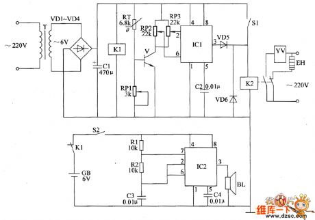
Bean sprouts automatic watering thermostats circuit diagram
Published:2011/6/14 3:03:00 Author:Lucas | Keyword: Bean sprouts , automatic watering , thermostats | From:SeekIC

The bean sprouts automatic watering thermostats circuit is composed of the power supply circuit, temperature detection control circuit and power failure alarm circuit, and the circuit is shown as the chart. Temperature detection control circuit is composed of the thermistor RT, potentiometers RP1 ~ RP3, transistor V, time-base integrated circuit IC1 and capacitor C2, diodes VD5, VD6, relay K2 and the control switch S1 . Power failure alarm circuit consists of the relay K1, switch S2, resistors R1, R2, capacitors C3, C4, and speaker BL and the time-base integrated circuit IC2. R1 and R2 use 1/4W carbon film resistors or metal film resistors. RP1 ~ RP3 use small organic solid potentiometers or variable resistors. RT chooses the thermistor resistor with negative temperature coefficient.
Reprinted Url Of This Article:
http://www.seekic.com/circuit_diagram/Control_Circuit/Temperature_Control/Bean_sprouts_automatic_watering_thermostats_circuit_diagram.html
Print this Page | Comments | Reading(3)

Article Categories
power supply circuit
Amplifier Circuit
Basic Circuit
LED and Light Circuit
Sensor Circuit
Signal Processing
Electrical Equipment Circuit
Control Circuit
Remote Control Circuit
A/D-D/A Converter Circuit
Audio Circuit
Measuring and Test Circuit
Communication Circuit
Computer-Related Circuit
555 Circuit
Automotive Circuit
Repairing Circuit
Code: