Control Circuit
Infrared remote control switch circuit with the PLL audio decoding circuit
Published:2011/6/19 20:33:00 Author:TaoXi | Keyword: Infrared remote control, PLL, audio decoding | From:SeekIC
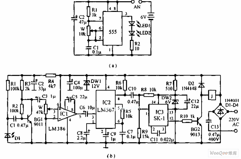
The infrared remote control switch circuit which uses the PLL audio decoding circuit is as shown in the figure, the emitter uses the multivibrator which is composed of the 555, the oscillation frequency is 1kHz to 20kHz. The receiver is composed of the infrared receiving amplifier, the audio decoder circuit and the sonic executive circuit. The infrared receiving tube needs to use with the transmitting tube. The infrared receiving amplifier is composed of the BG1 and IC1, the audio code circuit uses the audio code integrated circuit LM567 which has the phase locked loop, it requires the input signal not less than 25mV when this device is decoding, so we use the integrated power amplifier LM386 to get enough gain. The center frequency of LM567 is decided by the R5 and C7.
Reprinted Url Of This Article:
http://www.seekic.com/circuit_diagram/Control_Circuit/Infrared_remote_control_switch_circuit_with_the_PLL_audio_decoding_circuit.html
Print this Page | Comments | Reading(3)

Article Categories
power supply circuit
Amplifier Circuit
Basic Circuit
LED and Light Circuit
Sensor Circuit
Signal Processing
Electrical Equipment Circuit
Control Circuit
Remote Control Circuit
A/D-D/A Converter Circuit
Audio Circuit
Measuring and Test Circuit
Communication Circuit
Computer-Related Circuit
555 Circuit
Automotive Circuit
Repairing Circuit
Code: