Control Circuit
555 simple TV channels transformation remote controller circuit
Published:2011/6/15 20:54:00 Author:TaoXi | Keyword: 555, simple, TV channels, transformation, remote controller | From:SeekIC

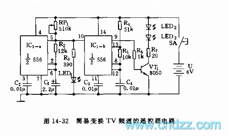
This remote control circuit uses the dual time base circuit 556 as the core, the circuit is as shown in figure 14-32.
In this figure, the astable multivibrator is composed of the IC1-a (1/2 NE556) and R2, RP1, C1, the oscillation frequency f1=1.4/(RP1+2R2)C1, you can make the resonance frequency to 1Hz by adjusting RP1. The output of it supplies the trigger pulse to the IC1-b(1/2NE556) time base circuit. The audio oscillator is composed of the IC1-b and R4, R5, C4. When there is the high level pulse, the audio oscillator starts working, the oscillation frequency f2=1.44/(R4+2R5)C4, the oscillation frequency of the figure parameters is about 2kHz. The pulse sequence is drived by VT1 to make the infrared launch tube LED to send out the 2kHz infrared modulation light.
Reprinted Url Of This Article:
http://www.seekic.com/circuit_diagram/Control_Circuit/555_simple_TV_channels_transformation_remote_controller_circuit.html
Print this Page | Comments | Reading(3)

Article Categories
power supply circuit
Amplifier Circuit
Basic Circuit
LED and Light Circuit
Sensor Circuit
Signal Processing
Electrical Equipment Circuit
Control Circuit
Remote Control Circuit
A/D-D/A Converter Circuit
Audio Circuit
Measuring and Test Circuit
Communication Circuit
Computer-Related Circuit
555 Circuit
Automotive Circuit
Repairing Circuit
Code: