Signal Processing
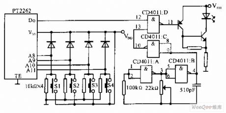
Infrared remote control 40Hz carrier wave signal generating circuit
Published:2011/6/26 5:51:00 Author:TaoXi | Keyword: Infrared remote control, 40Hz, carrier wave, signal generating circuit | From:SeekIC

The circuit that uses the infrared remote control 40Hz carrier wave signal generating circuit as the infrared transmitter is as shown in the figure, when you press one or several buttons of the S1-S4, the PT2262 gets power to work and it outputs the pulse data flow. At the same time, the pulse oscillator which is composed of the CD4011 and CD4011B starts working, the oscillation frequency can be adjusted to 40KHz by the 22Ω potentiometer, the frequency is the infrared carrier wave frequency. The output data flow of PT2262 modulates the 40KHz carrier wave in the CD4011D, then the output data flow drives the infrared led through the transistor to output the infrared signal.
Reprinted Url Of This Article:
http://www.seekic.com/circuit_diagram/Signal_Processing/Infrared_remote_control_40Hz_carrier_wave_signal_generating_circuit.html
Print this Page | Comments | Reading(3)

Article Categories
power supply circuit
Amplifier Circuit
Basic Circuit
LED and Light Circuit
Sensor Circuit
Signal Processing
Electrical Equipment Circuit
Control Circuit
Remote Control Circuit
A/D-D/A Converter Circuit
Audio Circuit
Measuring and Test Circuit
Communication Circuit
Computer-Related Circuit
555 Circuit
Automotive Circuit
Repairing Circuit
Code: