
Circuit Diagram
Index 1139
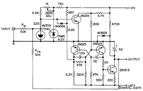
TRANSISTOR_VOLTMETER
Published:2009/7/24 1:57:00 Author:Jessie

Has input impedance of 1 megohm per volt. D-c amplifier provides gain of 100,000.-W. Mosinski, Transistor Voltmeter is Accurate, Linear, Electronics, 32;4, p 56-57. (View)
View full Circuit Diagram | Comments | Reading(2275)
BASIC_BISTABLE_MODULE
Published:2009/7/24 1:57:00 Author:Jessie

Can be used as flip-flop by connecting 1 to 7 and 4 to 8, than using 2 and 5 as inputs and 7 and 8 as outputs. Becomes binary counter stage when 2 and 5 are tied together for same arrangement. Other combinations of connections give one-shot mvbr, pulse generator, shift register, square-wave generator, or flip-flop.-A. I. Perlin, Selective Calling for Data Link Systems, Electronics, 33:18, p 108-110. (View)
View full Circuit Diagram | Comments | Reading(887)
Extended_range_Fahrenheit_temperature_sensor_single_supply
Published:2009/7/24 1:57:00 Author:Jessie

Fig, 13-2 This circuit is similar to that of Fig. 13-1, except that the temperature range is extended, -50° to +300°F, using a single supply. National Semiconductor, Linear Applications Handbook 1991. p 1076. (View)
View full Circuit Diagram | Comments | Reading(459)
422_kHz_NOTCH
Published:2009/7/2 9:18:00 Author:May
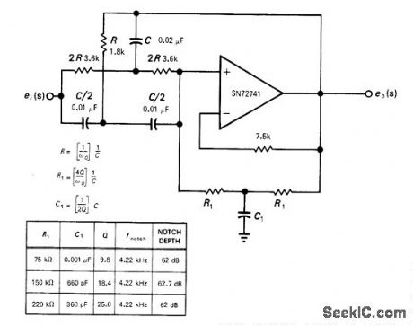
Circuit consists of positive unity-gain opamp, RC twin-T network, and T network R1C1 that determines circuit Q. Variable Q feature is controlled by single passive RC network. Center frequency of notch filter is about 4.22 kHz. Table gives values of R1 and C1 for three different values of Q.-H. T. Russell, Notch Filter Has Passive Q Control, EDN/EEE Magazine, July 1, 1971, p 43 and 45. (View)
View full Circuit Diagram | Comments | Reading(876)
7_MHz_±_50_kHz
Published:2009/7/2 9:17:00 Author:May

Requires no tuning capacitors. Collector-to-base iunctions of two 2N3053 transistors perform function of varactor diodes to provide tuning over range of about 50 kHz centered on 7 MHz. Capacitors marked M should be mica.-An Accessory VFO-the Easy Way, 73 Magazine, Aug. 1975, p 103 and 106-108. (View)
View full Circuit Diagram | Comments | Reading(1014)
PEAK_VOLTAGE_MEMORY
Published:2009/7/24 1:57:00 Author:Jessie

When properly balanced, will measure voltages in range from 0 to 10 cps with average error of 0.5%. Used with conventional digital voltmeter. Stores low-frequency positive and negative peak-voltage excursions in memory capacitor whose linear charge characteristic is controlled by operational-amplifier limit circuit. Used for measuring low-frequency voltages in servo systems.-W. V. Weiss, Peak-Voltage Memory Measures Low. Frequency Voltages Accurately, EEE, 10:7, p 50-55. (View)
View full Circuit Diagram | Comments | Reading(818)
BASIC_SHIFT_REGISTER_STAGE
Published:2009/7/24 1:56:00 Author:Jessie

If silicon controlled switch stage is off, shift pulse (less than 15 V) will not be coupled to next stage. Anode supply is interrupted just before shift pulse, to turn off all stages. Stored capacitor charge then determines which stages will be retriggered.- Transistor Manual, Seventh Edition, General Electric Co., 1964, p 432. (View)
View full Circuit Diagram | Comments | Reading(592)
D_C_PREAMP_FOR_VTVM
Published:2009/7/24 1:55:00 Author:Jessie

Prevents damage to transistors when making measurements with 1.5-v or 3-v range in semiconductor circuits. Feedback from Q3 to Q2 gives stability and linearity. Circuit can extend range of 1.5-v vtvm down to 500 or 150 mv full scale, but is sensitive to supply voltage variations and has open-circuit gain of only about 50.-A. K. Scidmore, Low-Cost Emitter-Follower Extends Voltmeter's Range, Electronics, 39:3, p 87. (View)
View full Circuit Diagram | Comments | Reading(665)
±15_V_converter
Published:2009/7/24 1:55:00 Author:Jessie

This circuit provides both +15-V and -15-V outputs at 30 mA, from a 6-V battery. However, a 30-kHz clock signal is required to drive a square-wave generator. (View)
View full Circuit Diagram | Comments | Reading(681)
5_A_steyo_down_PWM_regulator
Published:2009/7/24 1:55:00 Author:Jessie

Figure 7-47 shows the MAX787 connected to provide an output of +5 V at 5 A, with an input of 10 V to 40 V. The MAX787/88/89 provide 5-A outputs at 5 V, 3.3 V, and 3 V, respectively. Quiescent current is 8.5 mA. The ICs are also available in TO-3 packages. MAXIM NEW RELEASES DATA Book, 1994, P. 4-245. (View)
View full Circuit Diagram | Comments | Reading(580)
Basic_Fahrenheit_temperature_sensor
Published:2009/7/24 1:55:00 Author:Jessie

Fig. 13-1 This simple circuit requires only one three-terminal LM34, and produces an output voltage directly related to temperature. For example, if Vout is 0.72 V, the temperature is 72°F. Accuracy is ±0.4°F. The TO-46 package can be cemented or soldered to the mounting surface. If soldered to a metal surface, the ground pin is at the surface potential. If heat fins are used, thermal response time is speeded up. If soldered to a thermal mass, the reading will be steady despite small changes in temperature. National Semiconductor Linear Applications Handbook 1991, p 1076, (View)
View full Circuit Diagram | Comments | Reading(0)
500_KC_SHIFT_REGISTER
Published:2009/7/24 1:54:00 Author:Jessie

Basic nonsaturated flip-flop, using 52-step design procedure given, serves as building block for 500-kc counter and shift register.- Transistor Manual, Seventh Edition, General Electric Co., 1964, p 190. (View)
View full Circuit Diagram | Comments | Reading(816)
PEAK_SENSING_OPERATIONAL_AMPLIFIER
Published:2009/7/24 1:54:00 Author:Jessie
Operates as slideback sensing circuit to give d-c output that is proportional to positive peak of repetitive input signal. Will measure peaks of pulses as narrow as 1 nsec.- Transistor Manual, Seventh Edition, General Electric Co., 1964, p 371. (View)
View full Circuit Diagram | Comments | Reading(504)
SYMMETRICAL_SATURATED_FLIP_FLOP
Published:2009/7/24 1:53:00 Author:Jessie
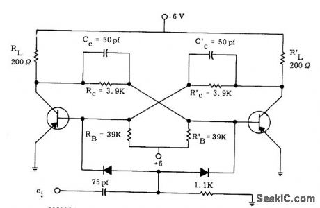
Developed for inexpensive 2N711 germanium pnp mesa switching transistors, to serve as building block for high-speed computer applications. Two or more flip4lops can be cascaded to form counter, or used as shift register by separating inputs. Close regulation is required for -6 V supply.-P. A. McInnis, Low-Cost Computer Circuits, Motorola Application Note AN-130, Nov. 1965. (View)
View full Circuit Diagram | Comments | Reading(670)
Precision_F_V_converter
Published:2009/7/24 1:53:00 Author:Jessie

Fig. 12-34 This circuit is similar to that of Fig. 12-33, except that the additional op amp permits the circuit to retain linearity over the full range of input frequencies. Trim the full-scale adjust pot so that a 10-kHz input produces a -10-V output. Then, set the offset-adjust pot for a -10-mV output with an input of 10 Hz. EXAR Corporation Databook 1990 p 5-124. (View)
View full Circuit Diagram | Comments | Reading(1017)
100_V_A_C_REFERENCE
Published:2009/7/24 1:52:00 Author:Jessie

Accurate 100-v rms source is used as reference voltage for divider to correlate vacuum-tube voltmeters. Meter is altered to zero-center, with new settle scale indicaing voltages up to 1.825 v on each side of 100-v center value. D-c voltage on one side of meter is held constant by zener diode, and is compared with positive voltage applied to other meter terminal by divider action without stabilization. Initial standardization is done by adjusting input controls for 100-v output as determined by reference standard. Output potentiometer is then adjusted to make meter tor respond (center of scale). Three diodes protect meter when unit is turned on.-Standardized AC Voltage Reference Source, Electronic Circuit Design Handbook, Mactier Pub. Corp., N.Y., 1965, p 151. (View)
View full Circuit Diagram | Comments | Reading(541)
Regulated_15_V_converter
Published:2009/7/24 1:52:00 Author:Jessie

This circuit delivers a 15-V output to a 50 mA load from a 6-V battery. Efficiency is 78%. Regulation is within 0.05% over a wide range of output loads, with a typical temperature coefficient of 50 ppm/°C. (View)
View full Circuit Diagram | Comments | Reading(593)
VOLTAGE_DIP_COUNTER
Published:2009/7/24 2:04:00 Author:Jessie

Each time a-c line voltage drops below adjustable threshold level, thyratron fires and operates electromagnetic counter. Used to count dips that might affect computer operation.-T. D. Koranye, Thyratron Monitors Line-Voltage Dips, Electronics, 34;1, p 126. (View)
View full Circuit Diagram | Comments | Reading(564)
Remote_temperature_sensor_grounded_sensor
Published:2009/7/24 2:04:00 Author:Jessie

Fig. 13-4 This circuit uses the basic LM34 (Fig. 13-1) where the sensor must be located some distance from the readout circuitry. With the values shown, the range is from +3°F to +100°F. If a 50-kΩ pot is used in place of the 20-kΩ fixed resistance, the gain can be adjusted to accommodate various twisted-pair lengths (between sensor and readout). Note that the LM34 is grounded in this configuration. National semiconductor Linear Applications Handbook 1991 p 1076. (View)
View full Circuit Diagram | Comments | Reading(675)
OSCILLATOR_OUTPUT_STAGE
Published:2009/7/24 2:04:00 Author:Jessie

Used with incremental-tuning precision R-C oscillator for testing and aligning equipment having sharp resonances. oscillator signal is fed through phase splitter V2 to cathode followers V3 and V4 in push-pull, to provide symmetrical output when required. Will feed either 600-ohm unbalanced load or two 300-ohm outputs balanced with respect to ground, with 10 mw maximum output.-J. H. Reyner, Precision Oscillator with Incremental Tuning, Electronics, 33:16, p 76-78. (View)
View full Circuit Diagram | Comments | Reading(600)
| Pages:1139/2234 At 2011211122112311241125112611271128112911301131113211331134113511361137113811391140Under 20 |
Circuit Categories
power supply circuit
Amplifier Circuit
Basic Circuit
LED and Light Circuit
Sensor Circuit
Signal Processing
Electrical Equipment Circuit
Control Circuit
Remote Control Circuit
A/D-D/A Converter Circuit
Audio Circuit
Measuring and Test Circuit
Communication Circuit
Computer-Related Circuit
555 Circuit
Automotive Circuit
Repairing Circuit