
Circuit Diagram
Index 1123
Single_chip_audio_amplifier_BTL_mono_3_W
Published:2009/7/23 23:59:00 Author:Jessie
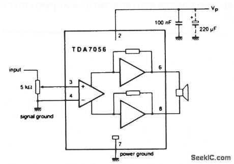
This circuit is similar to that of Fig. 1-27, except that no built-in volume control is provided. The supply range is from 3 V to 18 V. The circuit provides an output of 3 W, with an 11-V supply, into a 16-Ωload. Fixed, closed-loop voltage gain is 39 dB (11-V supply, 16-Ω load). (View)
View full Circuit Diagram | Comments | Reading(811)
5_A_negative_adjustable_voltage_regulator_with_safe_area_protection
Published:2009/7/23 23:59:00 Author:Jessie

This circuit uses the basic LAS79HG IC and external components to provide safe-operating-area protection. Characteristics are shown in Fig. 7-56B and 7-56C. (View)
View full Circuit Diagram | Comments | Reading(541)
Single_chip_audio_amplifier_BTL_3_W_with_volume_control
Published:2009/7/23 23:59:00 Author:Jessie
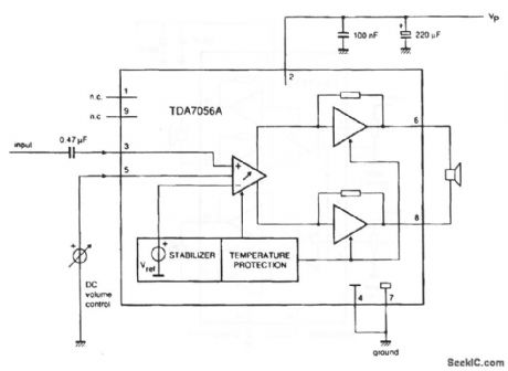
This circuit is similar to that of Fig. 1-27, except that the output is 3.4 W with a 12-V supply, into a 16-Ω load (View)
View full Circuit Diagram | Comments | Reading(859)
SWITCHING_MODE_SERVO_AMPLIFIER
Published:2009/7/23 23:58:00 Author:Jessie
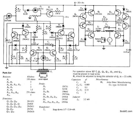
Input signal is used to control duration of relatively constant repetition-rate pulse signal, to give pulse-duration modulation. Repetition rote is 10 kc. Switching-mode output stage supplies power to control winding of two-phase servo motor.-Texas Instruments Inc., Transistor Circuit Design, McGraw-Hill, N.Y., 1963, p 483. (View)
View full Circuit Diagram | Comments | Reading(1783)
Basic_F_V_converter_with_temperature_compensation
Published:2009/7/23 23:58:00 Author:Jessie

Pig. 12-23 This circuit is similar to that of Fig. 12-19, but with temperature compensation. RX, D1, and D2 cancel the effect of timing capacitance TC. The manufacturer recommends that the circuit be checked with an oven if TC is critical. Resistance can be added in parallel or series with RX to offset the timing capacitor TC If TC is not critical, use 240 kΩ for RX. Again, set the 5-kΩ gain adjust for 10-V output with a 10-kHz input. National Semiconductor Linear Applications Handbook 1991 p 1301. (View)
View full Circuit Diagram | Comments | Reading(550)
600_Hz_THIRD_ORDER__LOW_PASS
Published:2009/7/3 2:51:00 Author:May

Butter-worth filtor using 741 or equivalent opamp provides gain of 6 dB in passband below 600-Hz cutoff,All components can be 5% tolerance.- H.M.Berlin, Design of Active Filters,with Experiments, Howard W Sams, Indianapolis, IN,1977,p 114-116. (View)
View full Circuit Diagram | Comments | Reading(715)
POWER_SUPPLY_MONITOR
Published:2009/7/3 2:50:00 Author:May

Circuit Notes
This circuit uses a tricolor LED display to indicate acceptable and unacceptable output voltages. One to set the upper voltage limit, the other, the lower voltage limit. When the monitored voltage is above the set maximum, the LED display turns red. Yellow turns on for voltages below the set minimum, and green turns on for voltages between the high and the low settings. The circuit does not need a separate power supply. It is powered by the voltage it monitors.The circuit can be adapted to monitor voltage differences between two power supplies. Should the monitored voltages differ by more than a set value, a visual or an audible alarm would warn the operator about the difference.The circuit can also be modified for remote monitoring and the use of a separate power supply. (View)
View full Circuit Diagram | Comments | Reading(1)
FSK_OSCILLATOR_FOR_EKG_RELAY
Published:2009/7/3 2:49:00 Author:May

Used in satellite system for relaying electrocardiograms in digital form. Input consists of 8-bit words obtained in serial form from universal asynchronous receiver-transmitter. Uses 8038 function generator that is switched between two adjustable trimmer resistors giving independently ad justable discrete audio frequencies for mark and space. Output is phase-coherent even though switching does not necessarily take place at zero-crossing points of sine wave. 0peration is much like that of FSK RTTY.-D. Nelson, Medical Lbata Relay via Oscar Satellite, Ham Radio, April 1977, p 67-73. (View)
View full Circuit Diagram | Comments | Reading(1461)
5_A_negative_adjustable_voltage_regulator_with_remote_sensing_and_current_limiting_at_6_A
Published:2009/7/23 23:58:00 Author:Jessie

This circuit uses the basic LAS79HG IC and external components to provide both remote sensing and current limiting. Characteristics are shown in Fig. 7-56B and 7-56C. (View)
View full Circuit Diagram | Comments | Reading(591)
Transition_slew_rate_tests
Published:2009/7/23 23:56:00 Author:Jessie


Figure 3-P shows a transition slew-rate test circuit for the MAX200/11/13. (Slew rate is covered in Chapter 6.) For reference, the slew rate is 5.5V/μs (typical) and 30V/μs (maximum) for the ICs involved. (View)
View full Circuit Diagram | Comments | Reading(690)
HEART_RATE_MONITOR
Published:2009/7/3 2:45:00 Author:May

Measures instantaneous frequency of such slow signals as heart beats (1 Hz) or 33-rpm motors (0.5 Hz) by measuring period T and inverting that quantity to obtain f. Operates from single 5-V supply for portable operation. Fast response time gives reading of heartbeat rate on digital display in two or three pulses. Optoisolator serving as sensor can be taped to almost any part of body because it responds to reflectivity changes caused by changing blood pressure,Accuracyis near 1%-G,Timmermann,Heartbeat-RateMonitor Captures VLF Signals.EDN Magazine,Oct,20.1977,p79-80. (View)
View full Circuit Diagram | Comments | Reading(0)
HIGH_VOLTAGE_SUPPLY
Published:2009/7/3 2:44:00 Author:May

Circuit NotesA 6 V battery can provide 100-150 Vdc center-tapped at a high internal impedance (not dangerous though it can inflict an unpleasant jolt). A 6.3 V transformer is connected in reverse with a transistor used in a Hartley oscillator configuration. The frequency of operation may be controlled by varying the value of the 10 K ohm resistor. The 10 μF capacitor must have a working voltage of at least 250 Vdc. (View)
View full Circuit Diagram | Comments | Reading(0)
LIGHT_SENSITIVE_OSCILLATOR
Published:2009/7/3 2:39:00 Author:May

Uses 555 timer connected so frequency increases directly with intensity of light. Free-running frequency and duty cycle of timer operating in astable mode are controlled by two resistors and one capacitor. R3 sets upper frequency limit at about 6.5 kHz, and dark resistance of photocell R2 sets lower limit at about 1 Hz. Loudspeaker provides audio output, while LED flashes for visual indication when frequency goes below about 12 Hz.Applications include detection of lightning flashes, use as optical radar for blind, and use as sunrise alarm.-C. R. Graf, Build a Light Sensitive Audio Oscillator, EDN Magazine, Aug. 5, 1976, p 83. (View)
View full Circuit Diagram | Comments | Reading(1199)
HIGH_VOLTAGE_GEIGER_COUNTER_SUPPL
Published:2009/7/3 2:39:00 Author:May

Circuit NotesThis circuit will generate about 300 volts dc-at a very low current,but enough for a GMtube. (View)
View full Circuit Diagram | Comments | Reading(1080)
SIMPLE_HIGH_VOLTAGE_SUPPLY
Published:2009/7/3 2:37:00 Author:May

Circuit NotesA light dimmer, a 1 pF capacitor and a 12 V car ignition coil form the simple line powered HV generator. The current in the dimmer is shown in Fig. B. At times t1, t2,..., set by the dimmer switch, the inner triac of the dimmer switches on, and a very high and very fast current pulse charges the capacitor through the primary of the induction coil. Then at a rate of 120 times per second for a 60 Hz line, a very high voltage pulse appears at the secondary of the coil. To obtain an HV dc output, use a voltage doubler. D1 and D2 are selenium rectifiers (TV 18 Siemens or ITT) used for the supply of television sets. High value output shock protection resistors, R, are recommended when suitable. (View)
View full Circuit Diagram | Comments | Reading(2568)
SINGLE_IC_AUTO_ALARM
Published:2009/7/3 2:36:00 Author:May


See (a) for the timing information for the alarm circuit in (b). When leaving your vehicle, flip the arming switch and close the door to arm the device. Subsequent opening of an entrance triggers both timers.After the expiration of the entry delay timer, the alarm sounds for a time determined by the second timer.The value of R should be less than 1 KΩ. If you use an incandescent lamp instead of a resistor, you get an extra function-an open-entrance indicator. By keeping the resistance low, you avoid false tripping should water collect under the hood. If your door switch connects the courtesy light to 12 V rather than ground, use a single transistor as an inverter at the input. (View)
View full Circuit Diagram | Comments | Reading(711)
UART_FOR_EKG_RELAY
Published:2009/7/3 2:35:00 Author:May

After electrocardiogram is converted to digital form by commercial A/D converter, circuit shown takes 8-bit word output of converter for processing by universal asynchronous receiver-transmitter (UART) to give required serial asynchronous code for transmitter of satellite relay system, with start, stop, and parity bits added to data under control of 19.2-kHz external clock. This serial output is then used to control FSK oscillator that switches between two discrete audio frequendes to give signal required for transmission through satellite. Article covers operation of UART in detail.-D. Nelson, Medical Data Relay via Oscar Satellite, Ham Radio, April 1977, p 67-73. (View)
View full Circuit Diagram | Comments | Reading(878)
F_M_MODULATOR_FOR_TAPE_RECORDER
Published:2009/7/24 4:51:00 Author:Jessie
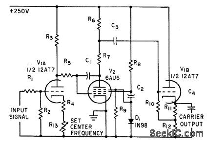
Miller-effect transitron oscillator V2 generates 7.5-kc carrier that is frequency-modulated by low-frequency action potentials from nerve fibers, to permit recording on ordinary tape recorder.-K. D. Broadfoot, F-M Magnetic Tape System Records Low-Frequency Nerve. Fiber Potentials, Electronics, 34:28, p 66-67. (View)
View full Circuit Diagram | Comments | Reading(751)
LOW_COST_ULTRA_HIGH_VOLTAGE_GENERATOR
Published:2009/7/3 2:32:00 Author:May
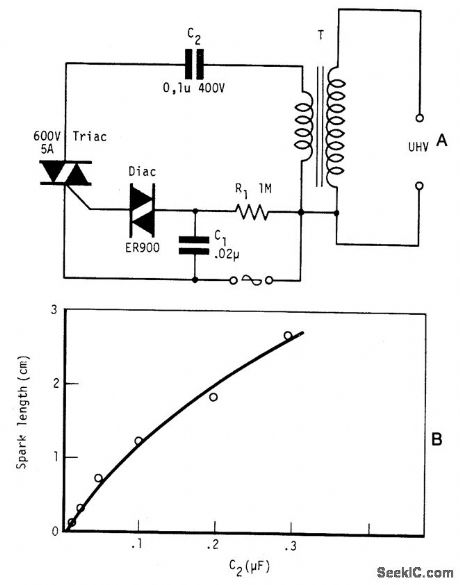
Circuit NotesBy repetitively charging and discharging a capacitor through the primary of an induction coil with a high voltage, an ultra high emf is induced in the secondary. Switching is performed by the triac, triggered by the disc at times set by C1 and R1. With a 12 V car ignition coil for example, the length of sparkgap obtained is 12 mm of air for C2 = 0.1μF. If the dielectric strength of air is assumed to be 3 kV/mm, this spark-gap length corresponds to 36 kV. From the curve shown in Fig. B, care must be taken in keeping the value of C2 below 1μF as the coil is liable to be seriously damaged at this value of C2. Power consumption is only about one watt. (View)
View full Circuit Diagram | Comments | Reading(1419)
SEMICONDUCTOR_FAIL-SAFE_ALARM
Published:2009/7/3 2:32:00 Author:May

False alarms produced by semiconductor failure are impossible with this burglar-alarm circuit equipped with relays. What's more, the circuit is virtually immune to false triggering. With a standby current of less than 0.1 mA, the circuit offers all the features an alarm needs: entry and exit delays, a timed alarm period, and automatic reset after an intrusion.One CMOS CD4093B quad NAND gate, IC1, supplies both logic and analog timing functions with the aid of Schmitt-trigger switching action. Relays make the circuit fail-safe in the alarm-active mode, even when the semiconductors fail. The relays are 12-V, with coil resistances of 250 Ω or more.Closing switch S1 initiates circuit operation. Capacitor C2 begins charging through resistor R2 and arming indicator LED1 lights. When pin 2 of ICla reaches its switching point, its output decreases, extinguishing LED1 and indicating that the exit delay has ended. That output also drives the base of Q1 low, so that if the emitter circuit completes to the VDD line, Q1 conducts. The circuit is now armed, and current drain drops to less than 0.1 mA.When the vehicle is entered, relay RY1 contacts close momentarily, completing the emitter circuit of Q1 and causing the RY2 contacts to close. Charging C4 through R7 determines the entry-delay period. If the system isn't turned off by opening S1 during this period, the oscillator circuit of IClc and ICld activates, and a rapid on/off horn-honking cycle kicks on with the aid of Q2 and RY3.The alarm cycle ends after about a minute, when C2 charges through R3 to the threshold voltage of ICla at pin 1. This voltage resets the timing circuit, readying it for another entry/alarm cycle. RY1 is connected for vehicles that use door switches connected to +12 V. For vehicles that use grounding door switches, the bottom of the RY1 coil should connect to + 12 V instead of ground. In the latter case, the polarity of C7 should be reversed. 'For home use, the R3C3 time constant should be increased to give a longer alarm. (View)
View full Circuit Diagram | Comments | Reading(1018)
| Pages:1123/2234 At 2011211122112311241125112611271128112911301131113211331134113511361137113811391140Under 20 |
Circuit Categories
power supply circuit
Amplifier Circuit
Basic Circuit
LED and Light Circuit
Sensor Circuit
Signal Processing
Electrical Equipment Circuit
Control Circuit
Remote Control Circuit
A/D-D/A Converter Circuit
Audio Circuit
Measuring and Test Circuit
Communication Circuit
Computer-Related Circuit
555 Circuit
Automotive Circuit
Repairing Circuit